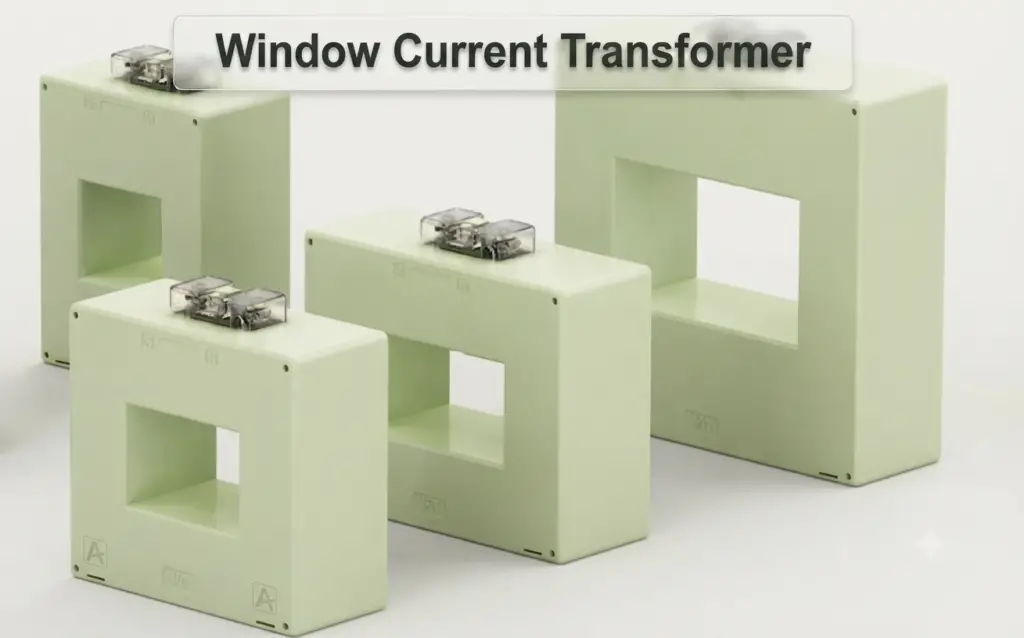
A Window Type Current Transformer is a type of current transformer (CT) in which the primary conductor is not an integral winding. Instead, the primary conductor, cable, busbar, or other current-carrying conductor passes through a central opening or window in the magnetic core. The secondary winding is permanently wound around the core to produce a reduced current proportional to the primary current.
Unlike a bar primary CT, a window type current transformer does not normally have a built-in primary conductor. The number of primary turns depends on how many times the conductor passes through the CT window. This provides flexibility for current measurement, especially in low- and medium-voltage distribution systems, switchboards, motor control centers, feeders, and protection circuits.
A Window type Current Transformer is widely used for metering, protection, energy monitoring, earth-fault protection, and electrical power measurement because it can be installed around an existing conductor without disconnecting or modifying the conductor in many applications.
Construction of Window Type Current Transformer
A Window Type Current Transformer consists primarily of a magnetic core, secondary winding, insulation system, and a central opening through which the primary conductor passes.
Unlike a wound-primary CT, the primary circuit is generally formed by an external cable, busbar, or conductor passing through the CT window.
1. Magnetic Core
The magnetic core provides a low-reluctance path for the magnetic flux produced by the primary current.
The core generally has the following characteristics:
- Made from laminated electrical steel or other suitable magnetic materials.
- Provides a low-reluctance path for magnetic flux.
- Laminations reduce eddy current losses.
- Core dimensions determine the CT’s magnetic performance and accuracy.
- The core design affects excitation current and saturation characteristics.
- Metering CTs may use cores optimized for measurement accuracy.
- Protection CTs may use cores designed to maintain acceptable performance during high fault currents.
- Special cores may be used for sensitive earth-fault or residual-current applications.
The magnetic core surrounds the window through which the primary conductor passes.
2. Window or Aperture
The central opening is the defining feature of a Window type Current Transformer.
The window:
- Allows a cable, busbar, or conductor to pass through the CT.
- Provides the magnetic coupling between the external primary conductor and the secondary winding.
- Determines the maximum conductor or busbar size that can be accommodated.
- Allows the CT to be installed around an existing conductor in suitable applications.
- Can accommodate one or multiple primary conductor passes.
- Influences the mechanical dimensions and installation flexibility of the CT.
The window must be sufficiently large to provide the required electrical clearance and accommodate the primary conductor without mechanical interference.
3. Secondary Winding
The secondary winding consists of multiple turns of insulated conductor wound around the magnetic core.
Its functions include:
- Producing a reduced current proportional to the primary current.
- Providing a standardized secondary current, commonly 1 A or 5 A.
- Supplying current to meters, protection relays, power analyzers, and other instruments.
- Providing the required current transformation ratio.
- Maintaining the specified accuracy within the rated burden and operating conditions.
The number of secondary turns determines the CT ratio when the number of primary turns is known.
4. Primary Conductor
Unlike a bar primary CT, the primary conductor of a Window type Current Transformer is normally external to the CT.
It may be:
- Power cable.
- Copper busbar.
- Aluminium busbar.
- Insulated conductor.
- Feeder conductor.
- Multiple conductors, depending on the CT design and application.
The conductor passes through the CT window and acts as the primary winding.
If the conductor passes through the window once, it represents approximately one primary turn.
If it passes through the window twice, it represents approximately two primary turns.
Therefore, the number of conductor passes affects the effective current transformation ratio.
5. Insulation System
The insulation system separates the secondary winding and magnetic core from the primary conductor and provides protection against electrical and environmental stresses.
Depending on the CT construction, insulation may include:
- Epoxy resin.
- Molded insulation.
- Polymer insulation.
- Insulated bobbins and winding materials.
- Protective enclosure materials.
The insulation system protects the CT against moisture, dust, contamination, mechanical damage, and electrical stress.
6. Enclosure and Terminals
Many Window Type Current Transformers have an insulated or molded enclosure that protects the core and secondary winding.
The enclosure may include:
- Secondary terminals.
- Polarity markings.
- Mounting holes or brackets.
- Terminal covers.
- Shorting provisions.
- Rating labels.
- Cable or busbar clearance arrangements.
The terminal markings may include S1 and S2, while the polarity relationship depends on the CT design and manufacturer.
Working Principle of Window Type Current Transformer
A Window Type Current Transformer works on the principle of electromagnetic induction.
When alternating current flows through the conductor passing through the CT window, it produces an alternating magnetic field around the conductor. The magnetic core collects and guides this magnetic flux.
The flux links with the secondary winding and induces a secondary current proportional to the primary current.
For an ideal current transformer:
Where:
- = Primary current
- = Secondary current
- = Number of primary turns
- = Number of secondary turns
For a conductor passing through the window once:
Therefore:
For example, consider a 1000/5 A Window Type Current Transformer.
The CT ratio is:
Therefore, when the primary current is 1000 A, the secondary current is approximately 5 A under ideal conditions.
If the primary current is 500 A:
Thus, a primary current of 500 A produces approximately 2.5 A on the secondary.
Key Working Points
- The external conductor acts as the primary winding.
- The conductor passes through the CT window.
- One conductor pass normally represents one primary turn.
- Multiple conductor passes can increase the effective primary turns.
- The magnetic core carries the flux produced by the primary current.
- The secondary winding produces a proportional reduced current.
- The CT provides electrical isolation between the primary circuit and connected measuring or protection equipment.
- The secondary current depends on the primary current, primary turns, and secondary turns.
- The CT ratio must be selected according to the application.
⚠️ Safety Warning (IMPORTANT): Never leave the secondary circuit of an energized current transformer open. An open CT secondary can develop dangerously high voltage, which can cause insulation failure, arcing, equipment damage, or serious injury. Always keep the secondary connected to its rated burden or safely short-circuited when required.
Types of Window Type Current Transformer
Window Type Current Transformers are available in different forms based on their construction, installation method, window shape, and application. The commonly used types include:
- Solid-Core Window CT: A solid-core Window Type Current Transformer has a continuous magnetic core with a fixed central opening. The primary conductor passes through the window during installation. It is commonly used in switchboards, distribution panels, MCCs, feeder circuits, energy monitoring systems, and protection circuits.
- Split-Core Window CT: A split-core CT has a magnetic core that can be opened and installed around an existing conductor without disconnecting it. This makes it suitable for energy audits, building energy monitoring, retrofit projects, temporary measurements, distribution monitoring, and existing electrical installations. The core must be properly closed to maintain the specified magnetic performance.
- Rectangular Window CT: A rectangular Window Type Current Transformer has a rectangular aperture designed to accommodate large cables or busbars. It is commonly used in switchgear, busbar systems, large distribution boards, industrial feeders, and high-current measurement systems.
- Ring-Type Window CT: A ring-type CT uses a circular magnetic core with a central opening through which the primary conductor passes. It is commonly used for cable current measurement, metering, protection, earth-fault detection, and residual-current measurement.
- Multi-Ratio Window CT: Some Window Type Current Transformers provide multiple secondary taps to obtain different current ratios from the same CT. Typical ratios may include 100/5 A, 200/5 A, 400/5 A, and 600/5 A. The available ratios depend on the manufacturer’s winding arrangement and specified terminal connections.
Technical Specifications of Window Type Current Transformer
The electrical, insulation, thermal, and mechanical specifications of a Window Type Current Transformer depend on its design, window dimensions, and intended application. Typical specifications include the following.
Electrical Specifications
- Primary Current: Commonly available from relatively low current ratings to several thousand amperes, depending on the CT design and application.
- Secondary Current: Standard secondary ratings are generally 5 A or 1 A.
- Current Ratio: Typical ratios include 50/5 A, 100/5 A, 200/5 A, 400/5 A, 600/5 A, 800/5 A, 1000/5 A, 1500/5 A, 2000/5 A, and higher ratings for specialized applications.
- Rated Burden: The CT burden may range from a few VA to several tens of VA, depending on the CT application.
- Accuracy Class: Metering CTs may use classes such as 0.2, 0.5, 1.0, and 3.0, while protection CTs may use classes such as 5P and 10P.
- Protection Class: Protection CTs may be specified using combinations such as 5P10, 5P20, 10P10, and 10P20, depending on the protection scheme.
- Knee Point Voltage (KPV): Protection Window CTs used with differential and high-impedance protection schemes may be specified by their Knee Point Voltage (KPV). The required value depends on the protection relay, CT design, secondary resistance, and connected burden.
- Frequency: Normally designed for 50 Hz or 60 Hz systems.
System and Insulation Specifications
The insulation requirements depend strongly on the system voltage, CT construction, and installation arrangement.
- System Voltage: Window CTs are available for low-voltage, medium-voltage, and, depending on construction, higher-voltage applications.
- Power-Frequency Withstand Voltage: Selected according to the applicable system insulation level.
- Insulation Type: May include epoxy resin, molded insulation, polymeric materials, or other suitable insulation systems.
- Impulse Withstand Voltage: Window CTs used in higher-voltage applications may be specified for a particular lightning impulse withstand level.
- Insulation Resistance: Should remain within the manufacturer’s specified limits during commissioning and scheduled maintenance.
- Clearance and Creepage: The CT should provide adequate clearance and creepage distances for the applicable system voltage and installation environment.
- Insulation Material: Selected according to the required dielectric strength, thermal performance, environmental conditions, and CT construction.
Thermal and Mechanical Specifications
Because the primary conductor passes through the CT window and carries the full system current, the thermal and mechanical ratings of the Window Type Current Transformer are particularly important.
- Continuous Thermal Current: The CT should withstand its rated primary current continuously without exceeding the specified temperature rise.
- Short-Time Thermal Current (Ith): Defines the short-circuit current that the CT can withstand for a specified duration, commonly 1 second or 3 seconds.
- Dynamic Current Rating (Idyn): Defines the CT’s ability to withstand the mechanical forces produced by high peak fault currents.
- Window Size: The internal window dimensions determine the maximum cable, conductor, or busbar dimensions that can pass through the CT.
- Primary Conductor Passes: The number of times the primary conductor passes through the window affects the effective primary turns and, consequently, the CT ratio.
- Mounting Arrangement: The CT may be designed for panel mounting, cable mounting, busbar mounting, or other installation arrangements.
- Construction: Window CTs may be available in solid-core, split-core, molded, epoxy-cast, or other suitable constructions, depending on the application.
- Mechanical Strength: The CT should withstand the mechanical stresses and vibration associated with the installation and prospective fault conditions.
- Applicable Standards: Current transformers are commonly designed and tested according to standards such as IEC 61869-2 and IEEE C57.13, as applicable.
Window Type Current Transformer Ratio
The current ratio of a Window Type Current Transformer depends on the relationship between the primary conductor passes and secondary winding turns.
The ideal relationship is:
Where:
- = Primary current
- = Secondary current
- = Number of primary conductor passes
- = Number of secondary turns
Single Primary Pass
When the conductor passes through the window once:
For example, for a 500/5 A CT:
Therefore, the effective secondary winding has approximately 100 times as many turns as the single primary turn under the idealized turns-ratio relationship.
Multiple Primary Passes
A major advantage of a Window Type Current Transformer is that the primary conductor can sometimes be passed through the window multiple times.
For two primary passes:
The effective primary turns increase, and the effective CT ratio changes accordingly.
For example, a CT with a secondary winding of 100 turns and two primary passes has an ideal ratio of:
Thus, the effective ratio would be approximately 50/1 A under this simplified example.
However, the actual permissible number of primary passes and resulting ratio must always be confirmed from the manufacturer’s specifications.
Installation of Window Type Current Transformer
Correct installation is essential for obtaining accurate current measurement and reliable protection performance.
Installation Guidelines
Follow these practices when installing a Window Type Current Transformer:
- Select the CT with the correct primary current rating.
- Check the required window dimensions before installation.
- Ensure the cable or busbar fits comfortably through the CT aperture.
- Maintain the manufacturer’s specified clearances.
- Install the CT in the correct orientation.
- Verify the polarity markings.
- Connect secondary terminals according to the specified polarity.
- Tighten secondary connections to the manufacturer’s recommended torque.
- Keep secondary wiring as short as practical where appropriate.
- Ensure the total connected burden does not exceed the CT rating.
- Provide appropriate shorting facilities for the secondary circuit.
- Ensure the CT is mechanically supported.
- Prevent excessive mechanical stress on the CT enclosure or terminals.
- Keep the CT away from unnecessary heat sources.
- Protect the CT from excessive moisture, dust, and corrosive contamination.
- Never leave the secondary circuit open while the primary conductor is energized.
Orientation of Window CT
Correct CT orientation is particularly important in metering and protection applications.
The CT may have polarity markings such as:
- P1
- P2
- S1
- S2
The primary current direction and secondary polarity must correspond to the requirements of the connected meter, relay, or protection scheme.
Incorrect orientation can result in:
- Incorrect power measurement.
- Negative power factor indications.
- Incorrect energy measurement.
- Differential protection malfunction.
- Incorrect residual current calculations.
- Relay operation problems.
Always follow the manufacturer’s polarity markings and the protection or metering wiring diagram.
Maintenance of Window Type Current Transformer
A Window Type Current Transformer generally requires limited routine maintenance, but periodic inspection helps maintain accuracy and reliability.
Regularly:
- Inspect the CT enclosure for cracks or physical damage.
- Check the insulation for discoloration or deterioration.
- Inspect secondary terminals for looseness.
- Check for overheating at electrical connections.
- Clean dust and contamination from accessible surfaces.
- Check the mounting arrangement.
- Inspect secondary cables for damaged insulation.
- Verify the CT ratio when required.
- Verify polarity during commissioning or troubleshooting.
- Measure insulation resistance during scheduled maintenance where applicable.
- Check the connected burden.
- Inspect meters and protection relays for abnormal indications.
- Check for excessive heating using suitable inspection methods.
- Replace damaged CTs when repair is not reliable or permitted by the manufacturer.
For split-core CTs, also inspect the mating surfaces and locking mechanism to ensure that the core closes correctly.
Common Problems and Troubleshooting
| Problem | Possible Cause | Solution |
| Incorrect current measurement | Incorrect CT ratio, polarity, or loose secondary connection | Verify CT ratio, polarity, and secondary wiring |
| CT overheating | Excessive primary current, loose connection, or excessive burden | Check primary current, connections, and connected burden |
| Core saturation | Excessive fault current or unsuitable protection CT | Select an appropriate protection CT and verify excitation characteristics |
| Relay malfunction | CT saturation, polarity error, or wiring problem | Check CT polarity, ratio, burden, and secondary circuit |
| High secondary voltage | Secondary circuit left open | De-energize safely and reconnect or short the secondary |
| Ratio error | Incorrect CT selection or excessive burden | Verify CT ratio and ensure burden is within the rated value |
| Insulation failure | Moisture, contamination, aging, or electrical stress | Perform appropriate insulation testing and replace the CT if necessary |
| Inconsistent measurement | Loose split-core connection or poor core closure | Check core mating surfaces and locking mechanism |
| Incorrect power reading | CT polarity reversed | Verify P1/P2 and S1/S2 connections |
| Physical installation problem | Window too small for cable or busbar | Select a CT with a suitable window size |
| Excessive secondary voltage | High burden or open secondary | Check secondary circuit and connected burden |
| Protection failure during fault | CT saturation or unsuitable accuracy class | Review protection CT class, ALF, knee point, and burden |
Window Type Current Transformer and Saturation
CT saturation occurs when the magnetic core can no longer maintain the required relationship between primary and secondary current.
During normal operation, the CT core operates within an appropriate portion of its magnetization curve.
During a severe fault, the primary current can increase substantially. The CT may then require a high secondary voltage to force the required secondary current through the connected burden.
If the required voltage exceeds the magnetic capability of the core, the CT can approach saturation.
Saturation can cause:
- Distorted secondary current.
- Reduced secondary current magnitude.
- Incorrect relay operation.
- Delayed protection.
- Differential protection instability.
- Measurement errors during high-current conditions.
For protection applications, the CT should therefore be selected based on its accuracy class, Accuracy Limit Factor (ALF), burden, excitation characteristics, and application-specific requirements.
Window Type Current Transformer – Burst Risk and Safety
A Window Type Current Transformer does not normally have a built-in primary conductor. However, it is still exposed to the electrical and mechanical stresses generated by the primary conductor passing through the window.
During a short circuit, the primary conductor can carry a very high fault current. This produces strong electromagnetic forces around the conductor and can subject the CT assembly to mechanical and thermal stress.
If the CT is incorrectly selected or installed, excessive fault current can result in:
- Mechanical damage.
- Insulation damage.
- Core displacement.
- Enclosure damage.
- Secondary winding damage.
- Excessive heating.
The CT’s short-time thermal current (Ith) and dynamic current rating (Idyn) should therefore be suitable for the prospective short-circuit current of the installation.
The most important CT safety rule concerns the secondary circuit.
When the primary conductor is energized, the CT secondary must not be left open.
An open secondary can produce a very high voltage across the secondary terminals. This voltage can result in:
- Electric shock.
- Arcing.
- Insulation breakdown.
- Secondary winding damage.
- Equipment damage.
Therefore:
Never open-circuit an energized CT secondary.
When a meter or relay must be disconnected, use an appropriate CT test block or shorting arrangement designed for the application.
Applications of Window Type Current Transformer
A Window Type Current Transformer is widely used for measuring and monitoring AC current in electrical systems. Its open-window construction allows an existing cable, busbar, or conductor to pass through the core without requiring a separate primary winding. This makes it particularly useful for new installations as well as retrofit applications.
- Electrical Distribution Panels: Window CTs measure feeder and outgoing circuit currents for metering, monitoring, and protection.
- Switchboards: They monitor current in incoming and outgoing feeders and provide signals to energy meters, protection relays, and monitoring systems.
- Motor Control Centers (MCCs): Window CTs measure motor feeder currents and help monitor motor loading, overload conditions, and energy consumption.
- Energy Management Systems: They provide current signals for calculating electrical power, energy consumption, load profiles, and demand.
- Industrial Power Systems: Industries use window type current transformers for continuous current monitoring in feeders, transformers, motors, and other electrical equipment.
- Protection Systems: CTs supply secondary current to protection relays for detecting abnormal operating conditions and initiating circuit breaker operation.
- Earth-Fault Protection: Window CTs can detect residual or zero-sequence current and are commonly used for earth-fault protection.
- Retrofit Energy Monitoring: Their construction allows installation around existing conductors with minimal modification to the electrical system.
- SCADA and Automation Systems: CT outputs can be connected to PLCs, DCS, SCADA systems, and digital monitoring equipment.
- Commercial Buildings: They are used for submetering, load monitoring, and energy management in offices, malls, hospitals, and other large buildings.
- Renewable Energy Systems: Window CTs monitor current in solar, wind, and battery-based electrical systems.
Overall, a Window Type Current Transformer is a practical choice where accurate current measurement is required without installing a dedicated primary winding.
Advantages of Window Type Current Transformer
A Window Type Current Transformer provides several advantages over conventional wound-primary CT arrangements.
- Simple primary construction.
- No integral primary winding is normally required.
- External cable or busbar acts as the primary.
- Easy integration into distribution systems.
- Available in solid-core and split-core designs.
- Flexible primary conductor arrangement.
- Multiple primary passes can be used in suitable applications.
- Suitable for high-current measurement.
- Compact construction.
- Good electrical isolation between primary and secondary circuits.
- Suitable for metering and protection.
- Useful for retrofit applications.
- Available for cable and busbar installations.
- Can be used for earth-fault and residual-current applications.
- Suitable for industrial monitoring and energy-management systems.
Limitations of Window Type Current Transformer
Despite its advantages, a Window Type Current Transformer has some limitations.
- The window size limits the maximum conductor or busbar dimensions.
- Solid-core versions may require the primary conductor to be disconnected for installation.
- Split-core versions may have different accuracy and performance characteristics from solid-core CTs.
- Incorrect core closure in a split-core CT can affect measurement accuracy.
- Primary turns depend on conductor passes through the window.
- Very low primary currents may require specialized CT designs.
- Incorrect CT ratio can cause significant measurement errors.
- Excessive burden can increase CT error.
- Protection CTs can saturate during severe fault conditions if incorrectly selected.
- The secondary circuit must never be left open while energized.
- Physical installation space around the conductor may limit the available CT size.
Window Type Current Transformer vs Bar Primary CT
The primary difference between a Window Type Current Transformer and a Bar Primary CT is the construction of the primary circuit.
A Bar Primary CT contains an integral solid conductor that acts as the primary winding. In contrast, a Window Type Current Transformer has an opening through which an external cable or busbar passes to form the primary winding.
| Feature | Window Current Transformer | Bar Primary CT |
| Primary Construction | External conductor through window | Integral solid bar |
| Primary Winding | Usually external | Integral |
| Typical Primary Turns | One or more conductor passes | Usually one |
| Primary Flexibility | High | Limited |
| Installation | Conductor passes through window | Bar connected in series |
| Cable Measurement | Excellent | Limited |
| Busbar Measurement | Excellent | Suitable depending on design |
| Split-Core Option | Available | Generally not typical |
| Retrofit Application | Excellent | Limited |
| High-Current Application | Excellent | Excellent |
| Metering | Suitable | Suitable |
| Protection | Suitable | Highly suitable |
| Earth-Fault Application | Excellent in suitable configurations | Application dependent |
| Physical Requirement | Adequate window clearance | Suitable bar connection |
| Typical Applications | Feeders, panels, MCCs, energy monitoring | Switchgear, substations, high-current feeders |
Window Type Current Transformer vs Wound CT
The main difference between a Window Type Current Transformer and a Wound CT is the way the primary circuit is formed.
A Window Type Current Transformer uses an external conductor passing through the magnetic core opening as its primary winding. The conductor may pass through the window once or multiple times.
A Wound CT, on the other hand, has a physically wound primary winding around the magnetic core. This gives the designer greater control over the number of primary turns and is useful for specific low- and medium-current measurement applications.
The Window CT generally provides easier installation around cables and busbars, while a Wound CT provides greater control over primary winding construction.
Window Type Current Transformer vs Ring CT
A ring CT is essentially a common physical form of a Window Type Current Transformer in which the magnetic core has a circular opening.
The term ring CT generally describes the physical shape, whereas Window Type Current Transformer describes the construction in which the primary conductor passes through the opening of the core.
Therefore, many ring-type CTs can be considered a form of window-type CT.
Factors Affecting Window Type Current Transformer Accuracy
The accuracy of a Window Type Current Transformer depends on several electrical, magnetic, and installation conditions. The following factors can influence its measurement and protection performance:
- CT Burden: The connected burden includes meters, relays, test blocks, and secondary wiring. If the actual burden exceeds the rated burden, CT errors can increase.
- Core Saturation: High fault currents can drive the magnetic core toward saturation. This condition can distort the secondary current and affect protection performance.
- CT Ratio: The CT ratio should match the expected operating current. A CT with an excessively high primary rating may provide poor measurement resolution at low operating currents.
- Primary Conductor Position: The position of the primary conductor inside the window can affect CT performance. For high-accuracy applications, follow the manufacturer’s installation requirements.
- Number of Primary Passes: Multiple passes of the conductor through the CT window change the effective number of primary turns. Therefore, the number of passes must be considered when determining the effective CT ratio.
- Secondary Wiring: Long secondary cables add resistance and increase the total burden. Proper cable sizing helps maintain the required CT accuracy.
- Accuracy Class: Select a CT with an accuracy class suitable for the intended application. Metering CTs and protection CTs have different performance requirements.
- Temperature: Temperature variations can change winding resistance, insulation characteristics, and overall CT performance.
- Installation Conditions: Loose connections, moisture, contamination, vibration, and mechanical damage can affect the accuracy and reliability of a Window Type Current Transformer.
How to Select a Window Type Current Transformer
Select a Window Type Current Transformer based on the electrical system, conductor dimensions, measurement requirements, and protection requirements.
Consider the following parameters:
- Primary current.
- Secondary current.
- Current transformation ratio.
- System voltage.
- Frequency.
- Window dimensions.
- Cable diameter.
- Busbar dimensions.
- Number of primary passes.
- Accuracy class.
- Rated burden.
- Short-time thermal current.
- Dynamic current rating.
- Protection requirements.
- Insulation level.
- Mounting arrangement.
- Metering or protection application.
- Environmental conditions.
- Applicable standards.
For protection applications, also check:
- Accuracy Limit Factor (ALF).
- Excitation characteristics.
- Knee point voltage where applicable.
- Secondary resistance.
- Lead resistance.
- Total connected burden.
- Required fault-current performance.
For energy-monitoring applications, pay particular attention to the CT ratio and accuracy class at the expected normal operating current.
Window Type Current Transformer for Energy Metering
Window CTs are widely used with energy meters because they can provide a proportional current signal without directly connecting the high-current primary circuit to the meter.
For example, a 400/5 A Window Type Current Transformer provides approximately 5 A secondary current when the primary current reaches 400 A under ideal conditions.
The meter uses this secondary current along with the voltage signal to calculate electrical parameters such as:
- Current.
- Active power.
- Reactive power.
- Apparent power.
- Power factor.
- Energy consumption.
The CT ratio must be correctly configured in the energy meter or metering system. Incorrect CT ratio settings can result in significant energy measurement errors.
Window Type Current Transformer for Earth-Fault Protection
A Window Type Current Transformer can also be used for earth-fault detection.
In a typical residual-current arrangement, the phase conductors pass through the same CT window.
Under normal balanced conditions:
Therefore, the net magnetic flux in the CT core is approximately zero.
If an earth fault occurs, some current returns through the earth or another unintended path. The vector sum of the phase currents is no longer zero:
The resulting residual current produces magnetic flux in the core and induces a secondary current.
The protective relay can detect this current and initiate the required protection operation.
The exact CT construction and relay arrangement should be selected according to the protection scheme.
Conclusion
A Window Type Current Transformer is a versatile current transformer in which an external cable, conductor, or busbar passes through a window in the magnetic core to form the primary winding. Its secondary winding produces a reduced current proportional to the primary current for measurement, monitoring, and protection.
The number of primary conductor passes can influence the effective CT ratio, providing additional flexibility in suitable applications. Window CTs are available in solid-core, split-core, ring-type, rectangular-window, and other configurations for different electrical installations.
Their simple construction, flexible installation, suitability for cable and busbar measurement, and availability for both metering and protection make them widely useful in switchboards, distribution panels, MCCs, industrial feeders, energy-management systems, and protection schemes.
However, proper selection is essential. The CT ratio, accuracy class, burden, window dimensions, insulation level, short-time thermal current, dynamic current rating, and protection characteristics should match the electrical system.
For protection applications, the CT must also provide suitable performance during fault conditions without excessive saturation. For metering applications, the CT ratio and accuracy should be appropriate for the normal operating current.
Above all, the CT secondary must never be left open while the primary is energized. Proper installation, polarity, burden, shorting arrangements, and maintenance are essential for safe and reliable operation.
When correctly selected and installed, a Window Type Current Transformer provides a reliable and practical method of measuring electrical current and supplying accurate current signals to meters, monitoring systems, and protective relays.
Frequently Asked Questions
A Window Type Current Transformer is a CT in which the primary conductor passes through an opening in the magnetic core. The external conductor acts as the primary winding, while the secondary winding produces a reduced current for measurement or protection.
It is called a Window CT because the magnetic core contains a central opening, or window, through which the primary conductor passes.
A conventional Window CT generally does not have a separately wound primary winding. The external cable, conductor, or busbar passing through the window forms the primary winding.
Yes, where permitted by the CT design, the conductor can pass through the window multiple times. Each pass increases the effective number of primary turns and changes the effective CT ratio.
A Window CT uses an external conductor passing through an opening as the primary winding, whereas a Bar CT has an integral solid bar that forms the primary winding
Read Next:
- Current Transformer (CT): Definition, Working and Applications
- Types of Current Transformers (CT)
- Difference between Current Transformer(CT) & Potential Transformer(PT)
- Core Balance Current Transformer(CBCT)
- Accuracy Limit Factor of Current Transformer
- Bar Primary CT: Construction, Working & Applications