The turn-on voltage of a diode is the forward voltage at which the device starts carrying a meaningful amount of current. Represented by , this parameter is important when designing rectifiers, electronic switching circuits, signal detectors, and regulated power supplies.
A semiconductor diode conducts primarily in the forward direction, from its anode toward its cathode. However, the current flowing through it depends on the voltage applied across its terminals. Understanding the relationship between forward voltage and current helps engineers select suitable diodes and estimate circuit losses.
What Happens When a Diode Turns On?
A conventional semiconductor diode contains a PN junction formed by combining p-type and n-type semiconductor regions. When these regions meet, electrons and holes recombine near the junction, producing a depletion layer.
The depletion layer establishes an electric field that opposes the movement of charge carriers across the junction. When an external voltage is applied in the forward direction, this opposition is reduced, allowing more carriers to cross the junction.
As the applied voltage increases, the diode current rises gradually. After reaching a particular region of its current-voltage curve, the current begins increasing much more rapidly. This region is commonly associated with the cut-in voltage, also known as the knee voltage.
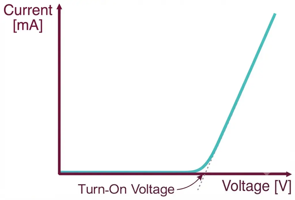
A practical diode does not have an exact switching point like an ideal electrical switch. Instead, the voltage at which it is considered to be conducting depends on the current level and the device characteristics.
For this reason, the forward voltage specified in a manufacturer’s datasheet should always be interpreted together with its test current and operating temperature.
Typical Forward Voltage Values for Common Diodes
Different diode technologies have different forward voltage characteristics. The semiconductor material, junction structure, and intended application all influence the voltage required to produce a particular current.
The following values provide approximate examples for comparison.
| Diode Category | Illustrative Forward Voltage |
| Silicon rectifier diode | 0.65–0.75 V |
| Germanium diode | 0.25–0.35 V |
| Schottky diode | 0.20–0.40 V |
| Red light-emitting diode | 1.7–2.1 V |
| Blue light-emitting diode | 2.8–3.5 V |
| White light-emitting diode | 2.9–3.5 V |
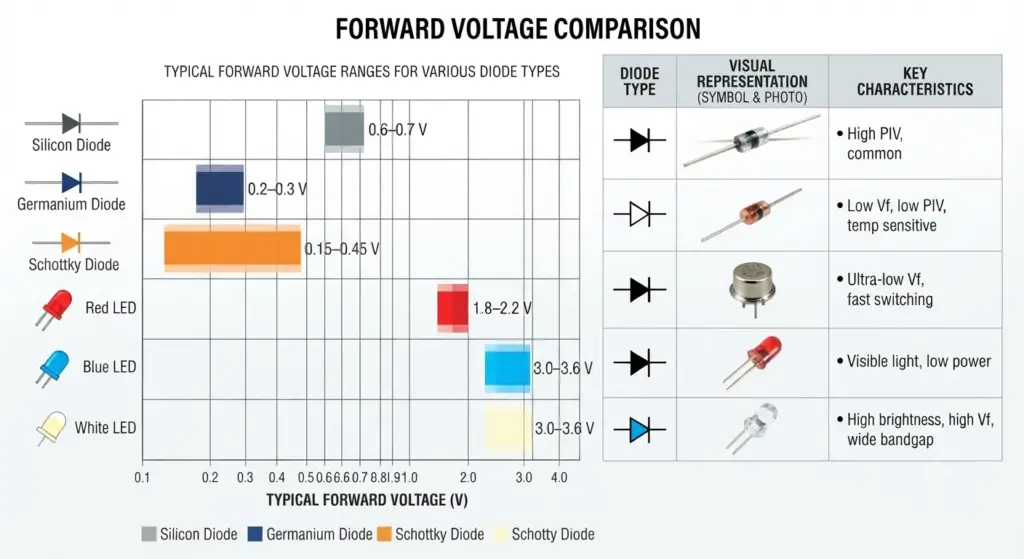
These ranges are representative rather than guaranteed limits. The actual forward voltage must be verified using the datasheet of the selected component.
Silicon Rectifier Diode
Silicon diodes are widely used in power conversion and general electronic applications. At suitable operating currents, their forward voltage is commonly close to 0.7 V.
They are found in bridge rectifiers, reverse-polarity protection circuits, and signal-switching applications. Their performance, availability, and range of voltage ratings make them useful for many circuit designs.
Germanium Diode
Germanium diodes typically have a lower forward voltage than conventional silicon PN-junction diodes. This characteristic can be beneficial in certain low-level signal and detector circuits.
However, germanium devices generally exhibit higher reverse leakage current and greater temperature sensitivity than comparable silicon devices. These characteristics must be considered when selecting them for practical applications.
Schottky Barrier Diode
A Schottky diode uses a junction between a metal and a semiconductor. Its forward voltage is often lower than that of a conventional silicon rectifier, reducing the energy dissipated during conduction.
These diodes are commonly used in low-voltage DC converters, high-frequency switching circuits, and power supplies where conduction losses are important. Their reverse leakage current and reverse-voltage rating also need careful consideration.
Light-Emitting Diode
A light-emitting diode (LED) produces light when electrical current passes through its semiconductor junction. Unlike ordinary rectifier diodes, its forward voltage depends strongly on the semiconductor composition and the wavelength of the emitted light.
Red LEDs generally operate at lower forward voltages than blue or white LEDs. Because the forward voltage varies between LED types, a suitable current-limiting resistor or constant-current driver is normally required.
What Determines the Forward Voltage of a Diode?
The forward voltage changes with operating conditions rather than remaining perfectly constant. Two particularly important factors are junction temperature and forward current.
Temperature Dependence
For a typical silicon PN-junction diode carrying a constant current, the forward voltage decreases as its junction temperature increases.
A representative temperature coefficient is approximately , although the actual coefficient depends on the device and operating point.
Consider a diode with a forward voltage of 0.72 V at 20°C. If its junction temperature increases to 60°C, the temperature change is:
Using the assumed temperature coefficient, the change in forward voltage is:
Converting the result into volts gives:
The estimated forward voltage at the higher temperature is:
Thus, the estimated forward voltage decreases from 0.72 V to approximately 0.644 V, assuming the current remains constant and the temperature coefficient is applicable over this range.
This calculation is an approximation. For accurate engineering work, use the temperature characteristics provided in the component datasheet.
Influence of Forward Current
The current flowing through a diode also affects its forward voltage. In a PN-junction diode, the current increases approximately exponentially with forward voltage over an appropriate operating range.
For an idealized silicon junction near room temperature, increasing the current by a factor of ten may increase the junction voltage by roughly 60 mV. Actual values vary with the device, temperature, and current range.
At higher currents, internal semiconductor resistance and contact resistance can contribute additional voltage drop. Therefore, a diode carrying several amperes may exhibit a different forward voltage from the same device operating at a small signal current.
When choosing a diode, engineers should compare the expected operating current with the forward-voltage curves in the manufacturer’s datasheet.
Calculating Power Loss in a Forward-Biased Diode
A conducting diode dissipates electrical power because a voltage drop exists across its terminals while current flows through it. This power is converted primarily into heat.
The approximate conduction power can be calculated using:
Where:
- represents diode power dissipation in watts.
- is the forward voltage in volts.
- is the forward current in amperes.
Worked Example
Suppose a diode operates with a forward voltage of 0.64 V and carries a current of 1.8 A. Its approximate conduction loss is:
The diode therefore dissipates approximately 1.15 W under these conditions.
The resulting heat must be considered when evaluating junction temperature, package limitations, and cooling requirements. At higher power levels, appropriate PCB copper area, thermal management, or a heat sink may be necessary.
This calculation represents conduction loss only. Switching losses and other circuit losses may also be relevant in high-frequency applications.
Why Forward Voltage Matters in Electronic Circuits
The forward voltage influences circuit efficiency, output voltage, and component temperature. Its importance varies according to the application.
Rectification in Power Supplies
Rectifier diodes convert alternating current into unidirectional current. During conduction, the diode voltage drop reduces the voltage available to the load.
In a conventional bridge rectifier, two diodes normally conduct in series during each half-cycle. The total conducting-path voltage drop is therefore approximately the sum of their individual forward drops.
This effect becomes especially significant in low-voltage power supplies, where even a small voltage loss can represent a substantial percentage of the output voltage.
Reducing Conduction Losses
Selecting a diode with a lower forward voltage can improve efficiency in circuits carrying substantial current. Schottky diodes are often considered for low-voltage converters because they can reduce conduction losses.
However, the lowest forward voltage does not automatically make a diode suitable for every application. Reverse leakage, maximum reverse voltage, surge-current capability, switching behavior, and thermal ratings must also be evaluated.
Voltage Clamping and Circuit Biasing
Diodes are sometimes used to limit voltage excursions or establish approximate voltage levels in electronic circuits. Connecting multiple diodes in series increases the total forward voltage drop under a given operating current.
However, the resulting voltage is not perfectly stable because forward voltage changes with current and temperature. Precision circuits generally require a suitable voltage reference or regulator when tighter voltage control is needed.
Protecting Electronic Components
A diode can help protect sensitive components against reverse polarity or unwanted voltage excursions when connected appropriately. Its forward voltage affects the voltage at which the protection path begins conducting appreciable current.
The diode must be selected according to the expected current, voltage transients, and thermal conditions. The circuit must also limit current to prevent the protection device from exceeding its ratings.
Conclusion
The turn-on voltage of a diode describes the forward voltage associated with the onset of appreciable current conduction. Its value depends on the diode technology, current level, and junction temperature rather than being a universal fixed number.
Silicon rectifiers generally have a forward voltage near 0.7 V under typical conditions, while Schottky and germanium diodes commonly operate at lower forward voltages. LEDs have higher forward voltages that depend on their emitted color and semiconductor construction.
Understanding these characteristics helps engineers calculate conduction losses, estimate rectifier output voltage, manage heat, and select suitable components for switching, protection, and power-conversion circuits.
Read Next: