Inductive reactance is the opposition offered by an inductor to changes in alternating current (AC). It is similar in some ways to the opposition provided by resistance in a DC circuit, but it arises from the magnetic effect of the inductor and depends on the frequency of the applied AC supply.
Inductive Reactance of a Coil
When a DC voltage is connected to an inductive coil, the current does not reach its final value instantaneously. As the current increases, the changing magnetic field around the coil induces a back EMF that opposes the change in current. The electric current gradually rises and approaches its steady-state value. For a practical coil, the final DC current is mainly limited by the resistance of its winding and can be determined using Ohm’s law:
The behavior changes significantly when an AC voltage is applied. Because the AC current is continuously changing, the magnetic field of the coil also changes continuously. This produces an induced EMF that opposes the variation in current. Therefore, the coil offers an opposition to AC that is determined not only by its inductance but also by the frequency of the applied voltage.
This opposition is called inductive reactance and is represented by . Its value is measured in ohms (Ω), just like resistance. The unit of inductive reactance is ohm (Ω). For an ideal inductor, inductive reactance is given by:
where:
- = inductive reactance in ohms (Ω)
- = AC supply frequency in hertz (Hz)
- = inductance of the coil in henries (H)
The equation shows that inductive reactance is directly proportional to frequency and inductance. Therefore, increasing the frequency of the AC supply increases the opposition offered by the coil to current. Similarly, a coil with greater inductance has a higher inductive reactance at the same frequency.
For example, if the frequency is doubled while the inductance remains unchanged, the inductive reactance also doubles. At DC, where the frequency is zero, the ideal inductor has zero inductive reactance after the transient condition has passed. In a practical coil, however, the winding resistance still limits the steady-state current.
Phase Relationship Between Voltage and Current
Inductive reactance also affects the phase relationship between voltage and current. In a purely inductive AC circuit, the current lags the applied voltage by 90°, or radians. This occurs because the inductor opposes changes in current through its induced EMF.
This behavior is opposite to that of a purely capacitive circuit, where current leads voltage by 90°. In a practical coil, the winding also has resistance, so the actual phase difference is less than 90°.
Thus, inductive reactance is an important property of coils in AC circuits because it determines how strongly an inductor opposes alternating current. Since increases with both inductance and frequency, the same coil can offer different levels of opposition when operated at different AC frequencies.
AC Inductor Circuit
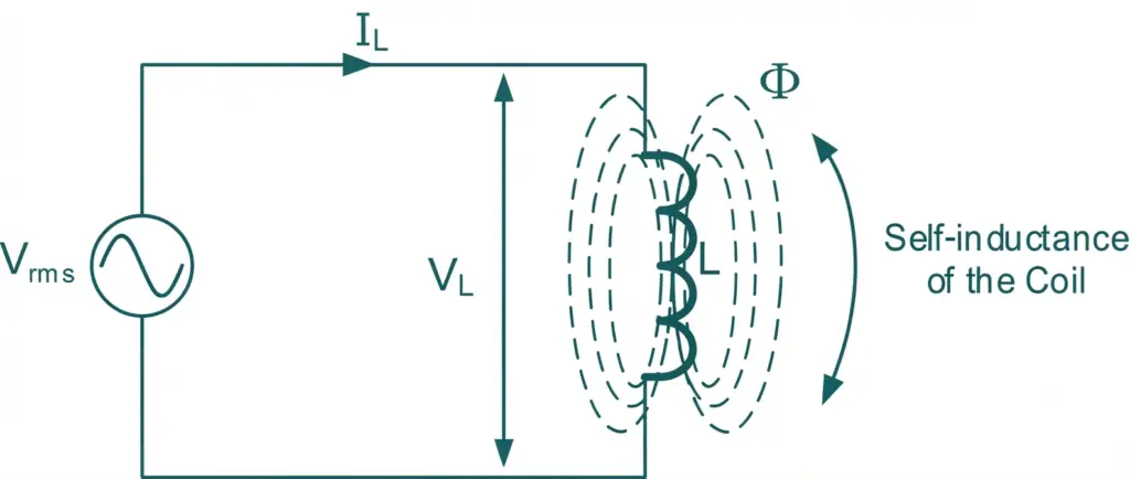
When an inductor is connected directly to an AC supply, the current through the coil continuously changes with the applied sinusoidal voltage. This changing current produces a changing magnetic field, which in turn generates a self-induced EMF or back EMF in the inductor. According to Faraday’s law, this induced EMF opposes the change in current.
The magnitude of the induced EMF depends on how rapidly the current changes. It is greatest when the rate of change of current is highest, which occurs as the current waveform passes through its zero crossing. Conversely, the rate of change of current becomes zero when the current reaches its positive or negative peak.
For an ideal inductive circuit, the voltage across the inductor leads the current by 90°. Therefore, when the applied voltage is at its positive or negative peak, the current is passing through zero. When the current reaches its maximum or minimum value, the voltage across the inductor is zero.
This continuous exchange between voltage and current is a characteristic feature of an AC inductor and explains why an inductor opposes changes in alternating current through its inductive reactance.
AC Inductor Phasor Diagram
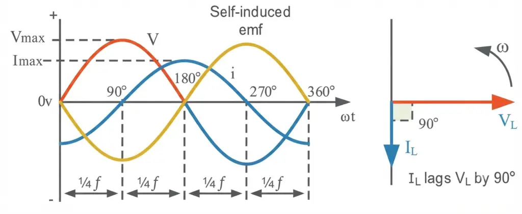
The phasor diagram of a pure inductive circuit shows the phase relationship between the applied voltage and the current. In an ideal inductor, the current waveform lags the voltage by which is equivalent to saying that the voltage leads the current by .
Taking the inductor voltage as the reference phasor, its phase angle can be written as . The corresponding current has a phase angle of . Therefore,
This phase difference can also be represented using sinusoidal waveforms. If the voltage is expressed as a sine function, the current waveform is shifted by 90° behind it. For an ideal inductor, the instantaneous current can therefore be written in the form:
or equivalently,
where:
- = instantaneous current
- = maximum current
- = angular frequency in rad/s
- = time in seconds
The phase relationship is a fundamental characteristic of a purely inductive AC circuit. Once the phase angle of either voltage or current is known, the phase of the other quantity can be determined directly.
For an ideal inductor, the relationship between voltage and current is:
Rearranging this expression gives the inductive reactance:
For a coil with inductance operating at frequency , the inductive reactance is:
Thus, the phasor relationship between voltage and current not only explains the 90° phase shift but also provides the basis for determining the inductive reactance of the coil.
Inductive Reactance Formula
The inductive reactance formula determines the opposition offered by a coil to alternating current. It depends on two main factors: the coil’s inductance and the frequency of the AC supply. Inductive reactance is represented by and is measured in ohms (Ω).
The formula for inductive reactance is:
where:
- = inductive reactance in ohms (Ω)
- = frequency of the AC supply in hertz (Hz)
- = inductance of the coil in henries (H)
The term represents the angular frequency :
The equation shows that inductive reactance depends directly on both frequency and inductance. If the inductance of a coil remains constant, increasing the supply frequency increases its reactance proportionally. Likewise, a coil with greater inductance presents greater opposition to AC at the same frequency.
At DC, the frequency is zero. Therefore, the ideal inductive reactance becomes zero:
This means an ideal inductor behaves like a short circuit in steady-state DC conditions. A practical coil, however, still has winding resistance, so its actual DC impedance is not zero.
As the frequency increases, the inductive reactance also increases. At very high frequencies, an ideal inductor can therefore present a very large opposition to current, approaching open-circuit behavior in the limiting case.
Hence, the key relationship is:
Low frequency → Low
High frequency → High
A graph of against frequency is therefore a straight line passing through the origin for a coil with constant inductance, demonstrating that inductive reactance is directly proportional to frequency.
Inductive Reactance Against Frequency
The relationship between inductive reactance and supply frequency can be understood directly from:
For a coil with constant inductance, increases linearly as the frequency of the applied AC supply increases. Therefore,
This means that a low-frequency AC signal encounters relatively little inductive opposition, whereas a high-frequency signal encounters much greater reactance.
At DC, the frequency is zero, so the ideal inductive reactance is:
Thus, after the transient period, an ideal inductor behaves like a short circuit to steady-state DC. As the frequency becomes extremely high, becomes very large, causing the ideal inductor to approach open-circuit behavior.
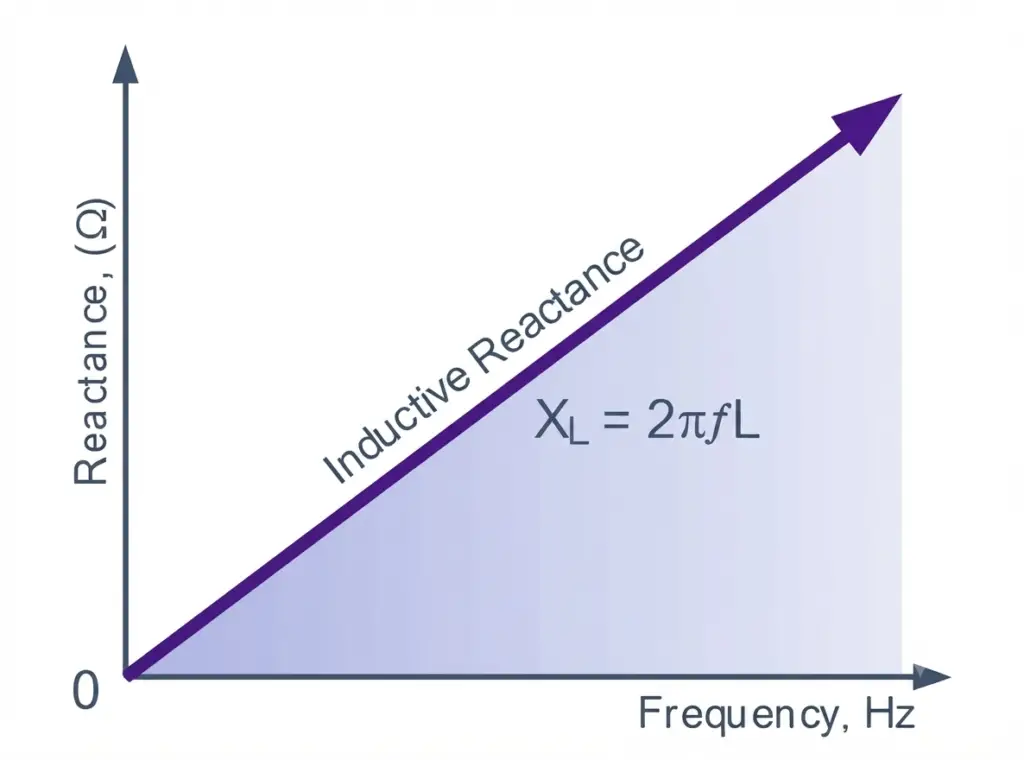
The graph of inductive reactance versus frequency is therefore a straight line for a constant-value inductor, with the reactance increasing directly with frequency.
Inductive Reactance Example No.1
A pure coil having an inductance of 250 mH is connected across a 120 V, 60 Hz AC supply. Assuming the coil has negligible resistance, calculate:
- The inductive reactance of the coil.
- The current flowing through the coil.
Given:
Step 1: Calculate Inductive Reactance
The inductive reactance is:
Substituting the given values:
Therefore, the inductive reactance of the coil is approximately:
Step 2: Calculate Current
For a pure inductive circuit, the current is determined by:
Therefore,
Hence, the current flowing through the coil is:
Answer: The coil has an inductive reactance of approximately 94.25 Ω and draws about 1.27 A from the 120 V, 60 Hz supply.
AC Supply Through an LR Series Circuit
A practical coil can never be considered a perfectly inductive component because its winding wire always has some electrical resistance. Therefore, an actual coil connected to an AC source can be represented by a resistor in series with an inductor . This combination is known as an series circuit or series circuit.
When an AC voltage is applied to the circuit, the total supply voltage is determined by the combined effect of the voltage across the resistance and the voltage across the inductance. These two voltages are not in phase, so they must be added as phasors rather than by ordinary arithmetic.
The voltage across the resistor, , is in phase with the circuit current. In contrast, the voltage across the inductor, , leads the current by 90°. Since the same current flows through both components in a series circuit, the current is commonly selected as the reference phasor and drawn horizontally.
The overall supply voltage is the phasor sum of and . Therefore, the supply voltage leads the current by an angle that is less than 90°. This angle is called the phase angle, represented by the Greek letter .
The impedance of the circuit combines the resistance and inductive reactance and is given by:
where:
- = impedance of the circuit in ohms
- = resistance in ohms
- = inductive reactance in ohms
The phase angle can be determined from:
Thus, the larger the inductive reactance compared with the resistance, the closer the phase angle approaches 90°. Conversely, when resistance is dominant, the phase angle becomes smaller.
This phasor relationship explains why the current in a practical inductive coil lags the applied voltage by less than 90°, unlike an ideal inductor where the phase difference is exactly 90°.
LR Series AC Circuit
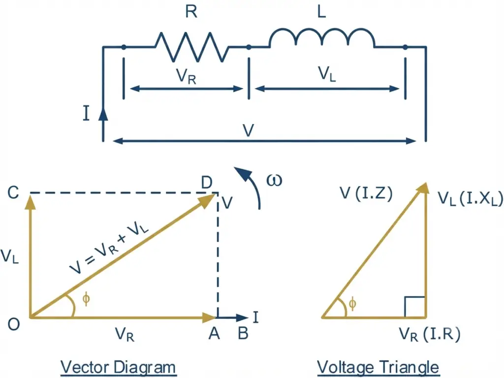
In an LR series AC circuit, the resistor and inductor carry the same current because they are connected in series. The current is therefore used as the reference phasor when representing the voltage and current relationships.
The voltage across the resistor, , is in phase with the current. In contrast, the voltage across the inductor, , leads the current by . The applied supply voltage is the vector or phasor sum of these two voltage components.
Since and are perpendicular phasors, the magnitude of the supply voltage can be obtained using the Pythagorean relationship:
The resulting voltage phasor forms a voltage triangle, where represents the horizontal component, represents the vertical component, and is the resultant.
In an AC circuit containing both resistance and inductive reactance, the ratio of voltage to current is called impedance, represented by . It is measured in ohms (Ω) and represents the total opposition offered by the circuit to AC current.
Dividing the voltage relationship by the circuit current gives the corresponding impedance relationship:
where:
- = circuit impedance in Ω
- = resistance in Ω
- = inductive reactance in Ω
This relationship can be represented graphically by an impedance triangle. The horizontal side represents resistance , the vertical side represents inductive reactance , and the hypotenuse represents the total impedance .
The phase angle of the LR circuit can also be obtained from the impedance triangle:
Thus, the impedance triangle provides a convenient way to understand the relationship between resistance, inductive reactance, impedance, and phase angle in an LR series AC circuit.
Impedance Triangle
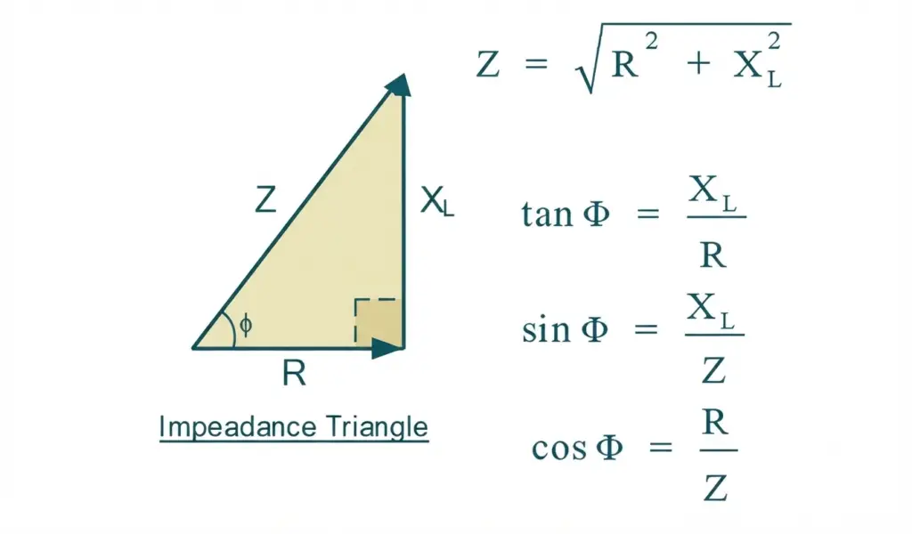
The impedance triangle is a graphical representation of the relationship between resistance , inductive reactance , and impedance in an LR series circuit. It is obtained by dividing the voltage triangle by the common circuit current.
In the triangle, the resistance forms the horizontal side, while the inductive reactance forms the vertical side. The impedance , which represents the total opposition to AC current, forms the hypotenuse.
Using the right-triangle relationship:
The phase angle between the circuit voltage and current can be determined from:
Therefore, the impedance triangle provides a simple way to determine the total impedance and phase angle of an LR series circuit from its resistance and inductive reactance.
Inductive Reactance Example No. 2
A solenoid coil has a resistance of 24 Ω and an inductance of 0.4 H. If the current flowing through the coil is 3 A at a frequency of 60 Hz, calculate:
a) The voltage of the supply.
b) The phase angle between the voltage and current.
Given:
a) Calculate the Supply Voltage
First, calculate the inductive reactance:
The impedance of the LR series circuit is:
Using Ohm’s law for an AC circuit:
Therefore, the supply voltage is approximately 453 V.
b) Calculate the Phase Angle
The phase angle is given by:
Therefore,
Hence, the current lags the supply voltage by approximately 80.96∘80.96^\circ.
Final Answers
- Inductive reactance:
- Impedance:
- Supply voltage:
- Phase angle:
- Current: lags the voltage by approximately
Power Triangle of an AC Inductor
The power triangle is another useful graphical representation for analyzing power in an AC circuit containing resistance and inductance. It shows the relationship between real power , reactive power , and apparent power .
In an RL series circuit, the current lags the applied voltage by the phase angle . The inductive component of the circuit causes reactive power to flow between the source and the magnetic field of the inductor. Reactive power is represented by and is measured in volt-amperes reactive (VAR).
For an inductive circuit, reactive power is given by:
where:
- = reactive power in VAR
- = RMS current in A
- = inductive reactance in Ω
For a practical coil that has both resistance and inductance, some electrical energy is converted into heat in the winding resistance. This component is the real or active power:
The total power supplied to the AC circuit is represented by apparent power SS:
where is measured in volt-amperes (VA).
These three quantities form a right-angled power triangle:
The angle of the power triangle is the same phase angle between the circuit voltage and current. Therefore:
The quantity is known as the power factor. For an inductive load, the power factor is lagging because the current lags the applied voltage.
In a purely inductive circuit, the phase difference is exactly . Ideally, the average real power consumed is zero because the inductor alternately stores energy in its magnetic field and returns that energy to the source during each AC cycle. However, the circuit still has reactive power and apparent power.
Thus, the power triangle provides a convenient way to understand how electrical power is divided into real power, reactive power, and apparent power in an AC inductive circuit.
Power Triangle
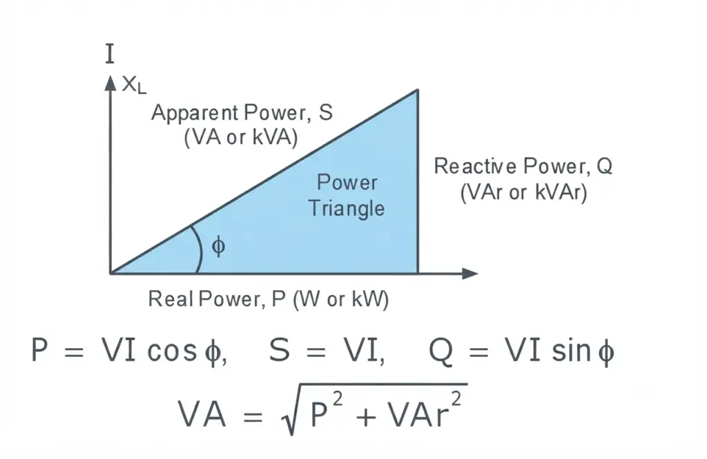
The power triangle represents the relationship between real power, reactive power, and apparent power in an AC circuit. For a practical inductor, the winding has a finite resistance, so the coil does not behave as a purely inductive component.
The winding resistance causes part of the electrical energy to be converted into heat. This component is the real power PP, measured in watts (W). At the same time, the inductance causes reactive power QQ, measured in volt-amperes reactive (VAR), as energy is alternately stored in and released from the magnetic field.
The combination of real and reactive power gives the apparent power SS, measured in volt-amperes (VA):
For a practical RL circuit:
and
The angle between and is the circuit phase angle , and the power factor is:
Therefore, although an ideal inductor consumes no average real power, a practical coil does consume real power because of the resistance of its windings. The impedance of the coil combines this resistance with its inductive reactance and determines the total opposition presented to the AC supply.
Conclusion
Inductive reactance is an important property of an inductor that determines how it opposes alternating current. It depends mainly on the inductance and frequency of the AC supply and is calculated using . As frequency or inductance increases, inductive reactance also increases.
The article also explains the behavior of inductors in AC and LR series circuits, including impedance, phase angle, voltage and impedance triangles, and power relationships. In a practical coil, winding resistance produces real power losses, while inductance contributes reactive power. Understanding these concepts is essential for analyzing AC circuits, selecting suitable components, and evaluating current, voltage, power factor, and power flow in inductive loads.
Read Next: