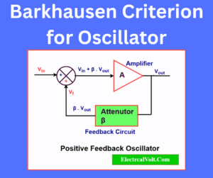
Voltage Doubler- Circuit Diagram, Half-Wave & Full-Wave
The voltage doubler produces two times DC voltage of the input AC peak voltage. This article describes the voltage doubler, its circuit diagram, types, working, … Read more
This article describes the shunt and series regulator and the differences between them. The main focus of this article is to distinguish between two kinds … Read more
This article describes IC 741 Op Amp basics. The operational amplifier (OP Amp) is a direct-coupled high gain amplifier. OP Amp usually consists of one … Read more
In this article, we will learn about power gain and voltage gain in dB. The letter dB stands for decibel. Bel or Decibel are the … Read more
Voltage, Current, and Power Gain of an Amplifier is the ratio of respective output quantity to input quantity. Here, quantity means voltage, current, and power. The … Read more
In this article, we will discuss the operation of a bistable Multivibrator Using 555 Timer. A Bistable multivibrator has two stable states (high and low). … Read more
In this article, we shall discuss an electronic circuit using a bipolar junction transistor (BJT) which operates as an amplifier, i.e. BJT as an amplifier. … Read more
In this article, we will discuss the differences between analog circuits & digital circuits. The analog and digital circuits are the basic building block of … Read more
The change of forward and reverse biasing of the diode makes the diode a switch. The diode is a two-terminal semiconductor device that has a … Read more
The basic difference between analog and digital signals is that an analog signal is a continuous signal whereas a digital signal is a discrete signal. … Read more