This article describes testing a bipolar junction transistor (BJT) using a digital multimeter (DMM). First, let’s understand what a BJT and a digital multimeter (DMM) are.
What is a Transistor?
A Bipolar Junction Transistor (BJT) is a semiconductor device with three terminals and two junctions. It is commonly used as a static switch or an amplifier in electronic circuits. The BJT, a transistor, is used in various fields, such as electronics, telecommunications, and computing.
A transistor comprises three alternating layers of P-type and N-type semiconductors. These layers are known as the emitter, base, and collector regions. Each layer is attached to a metal contact to create the three terminals of the transistor.
The three terminals of a transistor are named Emitter (E), Base (B), and Collector (C).
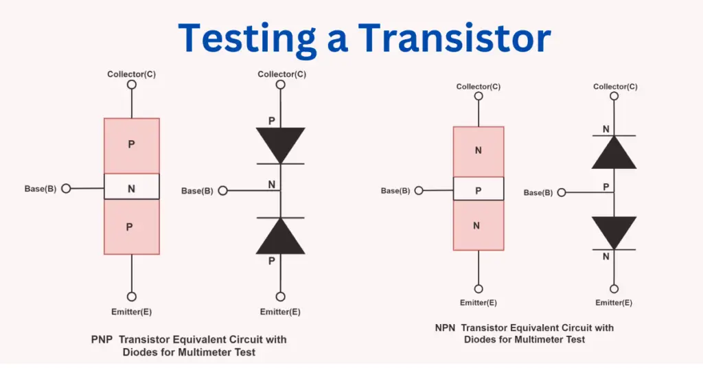
Depending on the construction, there are two types of transistors: NPN and PNP.
NPN Transistor:
Figure 1 illustrates the schematic diagram of an NPN transistor.
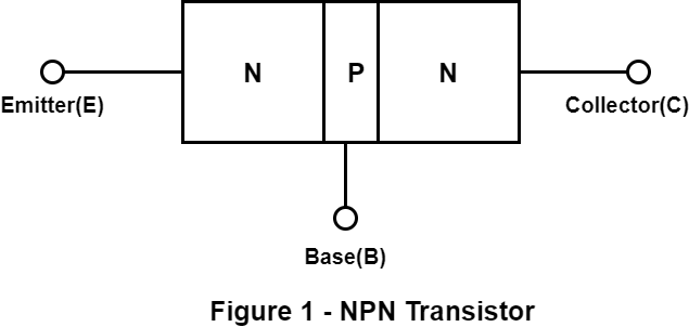
An NPN transistor is made by placing a P-type semiconductor layer between two N-type semiconductor layers. This means the emitter and collector regions are N-type, while the base region is P-type. An NPN transistor has two PN junctions – the emitter-base junction and the collector-base junction.
PNP Transistor:
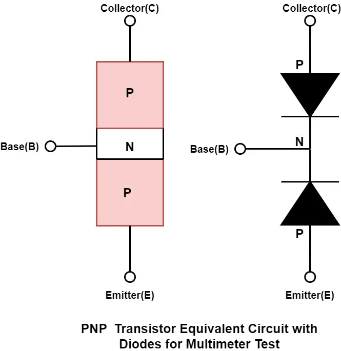
Figure 2 shows the schematic diagram of a PNP transistor.
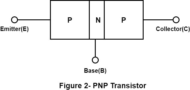
A PNP transistor is a bipolar junction transistor constructed by placing an N-type semiconductor layer between two P-type semiconductor layers. The emitter and collector regions of the transistor are made of P-type semiconductor material, while the base region is made of N-type semiconductor material.
The PNP transistor consists of two PN junctions: the emitter-base junction and the collector-base junction.
What is a Digital Multimeter?
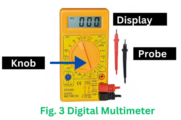
A digital multimeter, or DMM, is an electronic measuring device for testing electrical circuits. It measures parameters such as current, voltage, and resistance. In addition to this, a DMM is also used to test electronic components like transistors, diodes, and electric wires. Figure 3 shows a typical digital multimeter commonly used in various industries.
Combining the functions of different testing devices like voltmeter, ammeter, ohmmeter, etc., a digital multimeter is a single versatile unit. The best part is that digital multimeters are user-friendly and straightforward because they display measurement readings on a digital LCD or LED display.
The digital multimeter shown in figure-3 consists of three fundamental components:
- Display Screen – The display screen is a visual interface providing real-time measurement readings. It usually presents numerical data and other relevant information, such as units of measurement.
- A knob or Rotary Switch – A rotary switch selects measurement values such as amps, volts, ohms, and continuity.
- Input Jacks – Input jacks are ports used for test probes or leads. The positive probe is usually red, and the negative is black.
Now, we will discuss the testing procedure of transistors.
Testing of NPN Transistor Using Digital Multimeter
The process for testing an NPN transistor with a digital multimeter includes the following steps:
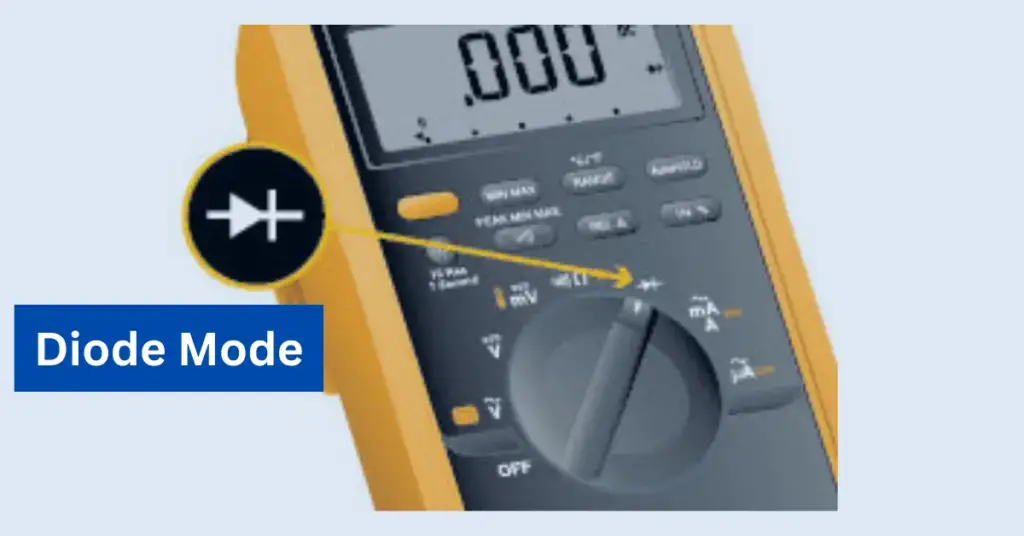
Step 1 – Turn on the digital multimeter and set the rotary switch to diode mode.

Step 2 – To test the Base to Emitter of BJT, connect the positive probe (red) to the base terminal of the transistor and the negative probe (black) to the emitter terminal. The diode formed between the base and emitter gets forward bias with this connection, and the meter displays the numerical value. If the DMM displays a voltage value for the transistor, generally between 0.45 V to 0.9 V, it indicates that the NPN transistor is functioning correctly.
Step 3 – To check the Base to Collector of a transistor, use a Digital Multimeter (DMM). Connect the DMM’s positive probe to the transistor’s base terminal and the negative probe to the collector terminal. The NPN transistor is in good condition if the DMM displays a voltage reading between 0.45 V and 0.9 V. The DMM displays the value because the diode formed between the base and collector gets forward bias with this connection.
Step 4 – To test a transistor’s emitter-to-base, connect the DMM’s positive probe to the emitter terminal and the negative probe to the base terminal. The NPN transistor functions correctly if the DMM displays OL (Over Limit). Here diode formed between emitter to base is reverse bias and does not conduct; therefore, DMM displays Over Limit( OL)
Step 5 – To test the NPN transistor for collector-to-base connection, connect the positive probe of the multimeter to the collector terminal and the negative probe to the base terminal. If the DMM display shows OL, the transistor is in good condition.
Step 6 – To test the Collector to Emitter of an NPN transistor, you need to connect the positive probe of a multimeter to the collector terminal and the negative probe to the emitter terminal. The transistor functions correctly if the digital multimeter (DMM) reads OL (Over Limit).
Step 7 – To test the Emitter to Collector of an NPN transistor, connect your digital multimeter’s positive probe to the transistor’s emitter terminal and the negative probe to the collector terminal. The transistor functions properly if the digital multimeter reads “Over Limit” (OL).
The transistor is considered faulty if the NPN transistor measurements do not follow these steps.
Testing of PNP Transistor with Digital Multimeter
The process for testing a PNP transistor using a digital multimeter includes the following steps:
Step 1 – First, turn on the digital multimeter and set the rotary switch to diode mode.
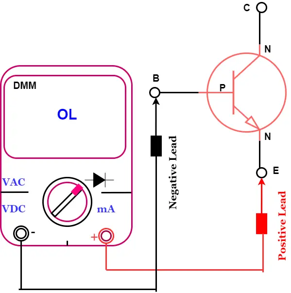
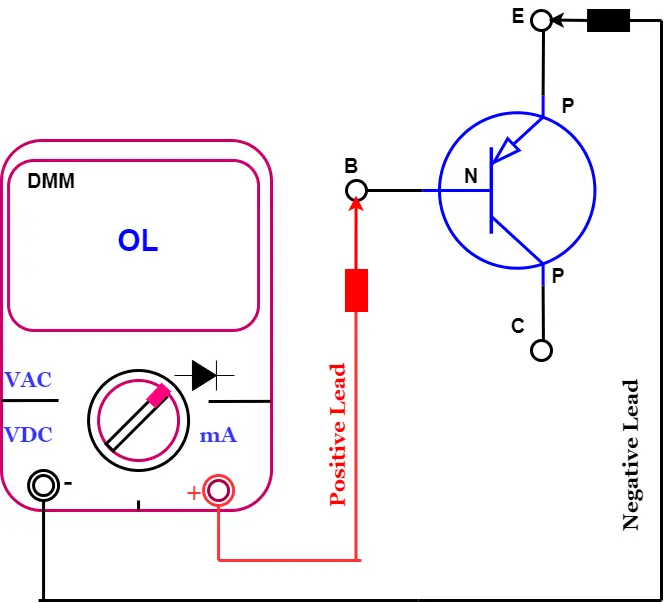
Step 2 – To test the Base to Emitter of a PNP transistor, follow these steps: Connect the positive probe (red) to the base terminal and the negative probe (black) to the emitter terminal. This connection causes the diode between the base and emitter to get reverse-biased. Therefore, the DMM should display OL. If the transistor is good, the DMM (Digital Multimeter) should show OL (Over Limit).
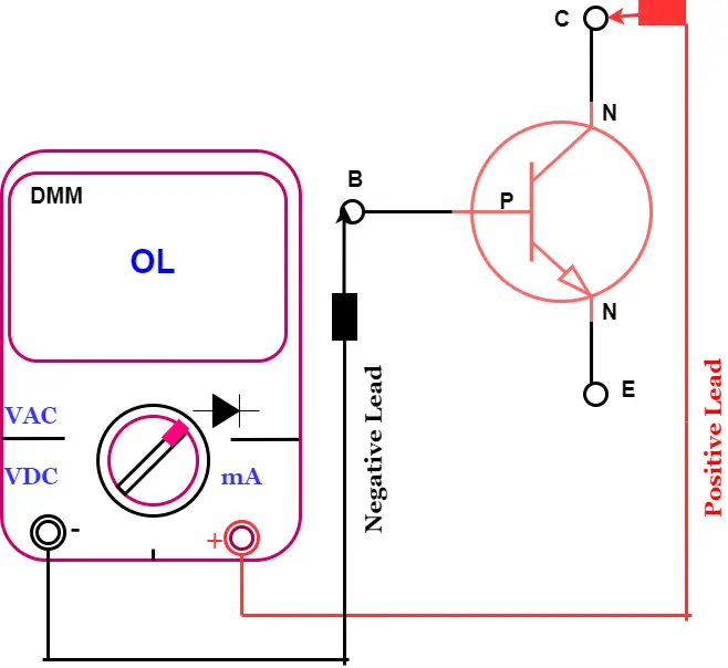
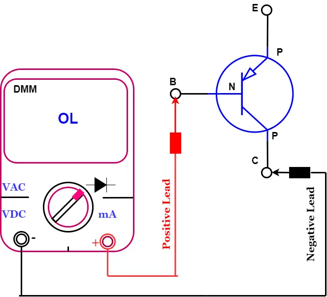
Step 3 – To test the Base to Collector of a PNP transistor, you need to connect the positive probe of the DMM to the base terminal of the transistor. Then, connect the negative probe of the DMM to the collector terminal of the transistor. This connection causes the diode between the base and emitter to become reverse-biased. Therefore, the DMM should display OL. If the DMM shows OL (Over Limit), the PNP transistor is in good condition.
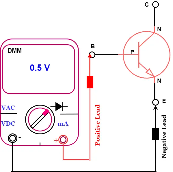
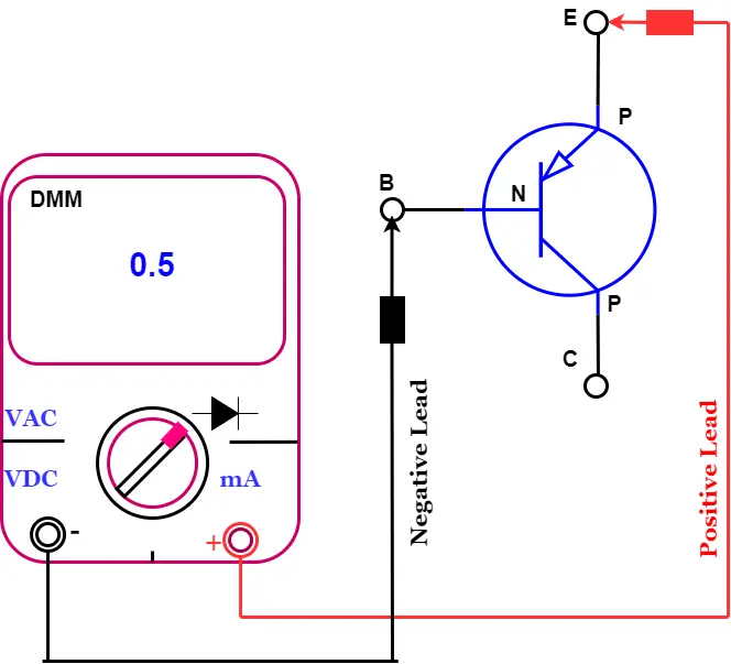
Step 4 – To test the Emitter to Base, connect the positive probe of the Digital Multimeter (DMM) to the emitter terminal of the transistor and the negative probe to the base terminal of the transistor. This connection causes the diode formed between the base and emitter to get forward bias, and the meter displays the numerical value of the voltage drop. The PNP transistor functions properly if the DMM displays a voltage drop between 0.45 V and 0.9 V.
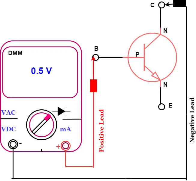
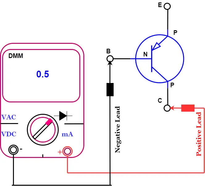
Step 5 – To test the Collector to Base of a PNP transistor, you need to connect the positive probe of the multimeter to the collector terminal of the transistor and the negative probe to the base terminal of the transistor. This connection causes the diode formed between the base and emitter to get forward bias, and the meter displays the numerical value of the voltage drop. The transistor is good if the multimeter displays a voltage drop between 0.45 V and 0.9 V.
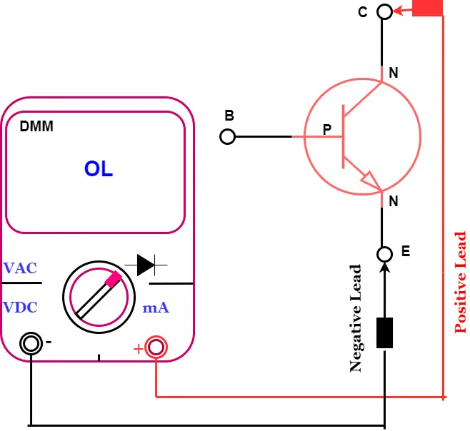
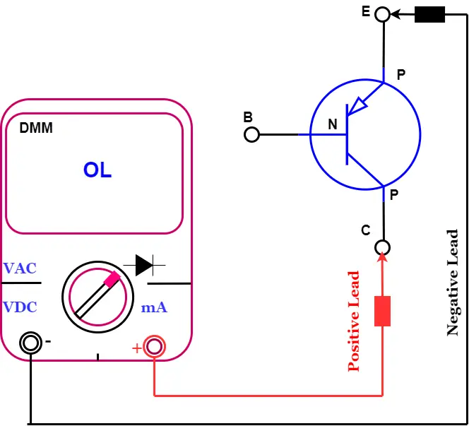
Step 6 – To test the Collector to Emitter of a PNP transistor, connect the positive probe of a multimeter to the collector terminal and the negative probe to the emitter terminal. The PNP transistor is good if the DMM reads OL (Over Limit).
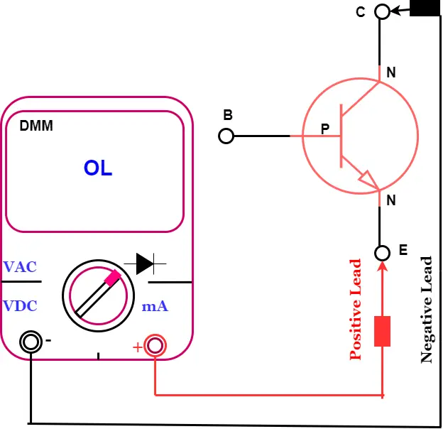
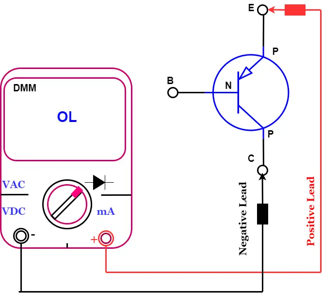
Step 7 – To test the Emitter to Collector on a PNP transistor, you must connect your digital multimeter’s positive probe to the transistor’s emitter terminal and the negative probe to the collector terminal. If the reading on the digital multimeter shows OL (Over Limit), then the transistor is good.
If the PNP transistor measures differently than these steps, it is faulty.
Points to be Noted
The process described above only confirms open or shorted junctions in a transistor when tested with a digital multimeter.
It is important to note that testing a transistor using a digital multimeter does not necessarily confirm that the transistor is functioning within its designed parameters. Therefore, this test should only be used to determine whether the transistor needs to be replaced.
It’s important to note that this test applies only to Bipolar Junction Transistors (BJTs).
Something I have noticed is that the collector always has lower reading than the emitter.