Electrical resistance is one of the most important concepts in electricity and electronics. It describes how strongly a material opposes the flow of electric current when a voltage is applied. The higher the resistance, the more difficult it is for current to pass; the lower the resistance, the easier it flows.
Measured in ohms (Ω), resistance plays a vital role in controlling current, protecting components, and ensuring the safe operation of electrical systems.
Whether you are studying basic electrical principles or working on complex circuit design, understanding the definition, unit, and practical use of resistance is essential.
Definition of Resistance
The property of the substance to resist the flow of electric current through it is known as resistance. The unit of resistance is Ohm. The conductors have free electrons moving randomly inside the metal, and on the application of voltage, the electrons start moving from the lower potential point to the higher potential point.
In simple terms, electrical resistance is the opposition a material offers to the movement of electrons when a voltage is applied. A higher resistance means less current will flow for a given voltage.
What is Electrical Resistance in Physics?
During the drifting of the electrons, the collision between the electrons and atom and molecule of the conductor takes place, and this collision impedes the path of flow of electrons. This impediment of the flow of electrons caused by the collision of electrons with atoms and molecules creates a hindrance. The electrical hindrance in the path of current flow is the electrical resistance.
In electricity and electronics, resistance is a fundamental concept that determines how much energy is needed to push electric charges through a conductor. This property is essential for controlling current in circuits.
Ohm’s Law and Resistance Formula
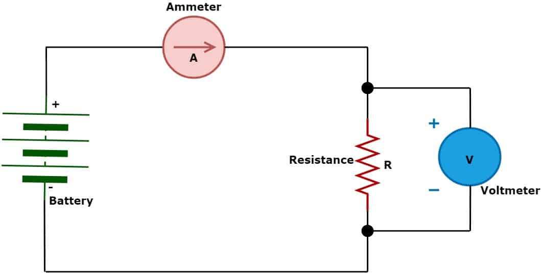
When we apply the voltage in a circuit, the current flows through the resistance. Let the voltage across resistance be V, and the current flowing in the circuit is I. The voltage across the resistance is proportional to the flow of electric current. According to Ohms’ Law,
V ∝ I
V = RI
R = V/I Where,
V – Voltage
I – Current
R – Resistance of the substance
Hence, we can define resistance as the ratio of the applied voltage to the current through the substance.
R = V/I
Unit of Resistance
Applying one volt of potential difference across the resistance causes a 1-ampere current to flow through it; then, the resistance is equal to 1 Ω.
The unit of resistance is volt per ampere orohm, named after George Ohm. The symbol of Ohm is omega (Ω ). The SI unit of the resistance is Ohm(Ω)
Unit for Resistance in Electrical Terms
R = V/I (Ohm’s Law)
= 1 Volt / 1 Ampere
R = 1 Ohm (Ω)
One ohm means the conductor allows a current of one ampere when a potential difference of one volt is applied.
Different Units of Resistance
The larger units of resistance are Kilo-Ohm, Mega-Ohm, and Giga-Ohm. The smaller resistance units are milli Ohm, Micro Ohm, and nano Ohm.
The relationship between different resistance units is given below. The different resistance units are:
| Unit Name | Symbol | Value in Ohms (Ω) | Scientific Notation | Practical Engineering Application |
| Gigaohm | GΩ | 1,000,000,000 Ω | 109 Ω | High-voltage cable insulation testing |
| Megohm | MΩ | 1,000,000 Ω | 106 Ω | Transformer winding insulation diagnostic checks |
| Kiloohm | kΩ | 1,000 Ω | 103 Ω | Electronics biasing circuits & signaling networks |
| Ohm (Base Unit) | Ω | 1 Ω | 100 Ω | Domestic heating elements, lightbulbs |
| Milliohm | mΩ | 0.001 Ω | 10-3 Ω | Earthing grids, power cable connection joints |
| Microohm | μΩ | 0.000001 Ω | 10-6 Ω | Circuit breaker contact resistance testing |
| Nanoohm | nΩ | 0.000000001 Ω | 10-9 Ω | Superconductor material research |
SI vs. CGS Units of Resistance (Historical Context)
While the Ohm (Ω) is the globally recognized SI unit for resistance, historical physics documentation and specific electromagnetic fields occasionally reference the CGS (centimeter-gram-second) system.
- The CGS Unit of Resistance: The base unit is known as the abohm (abΩ).
- The Conversion Factor: One abohm is equivalent to exactly 10-9 ohms (or 1 nanoohm).
Technical Accuracy Note: Several prominent online references mistakenly state that 1 abohm = 10⁹ Ω. In physical reality, the abohm is an incredibly small unit (1 abΩ = 0.000000001 Ω). Modern industrial engineering relies solely on the SI system to maintain mathematical clarity and prevent calculation errors.
How to Convert Between Resistance Units (With Examples)
When troubleshooting circuit systems or assessing insulation health, converting between base ohms and alternative prefixes is a daily necessity. Here are the step-by-step mathematical examples:
1. Converting Ohms (Ω) to Kilohms (kΩ)
- Method: Multiply the value by 10⁻³ (or divide by 1,000).
- Example: A 680 Ω resistor is equivalent to 0.68 kΩ.
2. Converting Ohms (Ω) to Megohms (MΩ)
- Method: Multiply the value by 10⁻⁶ (or divide by 1,000,000).
- Example: An insulation pathway reading 2,500,000 Ω is equivalent to 2.5 MΩ.
3. Converting Ohms (Ω) to Milliohms (mΩ)
- Method: Multiply the value by 10³ (or multiply by 1,000).
- Example: A heavy-gauge copper terminal connection with a resistance of 0.015 Ω converts directly to 15 mΩ.
4. Converting Ohms (Ω) to Microohms (μΩ)
- Method: Multiply the value by 10⁶ (or multiply by 1,000,000).
- Example: A set of main contacts in a medium-voltage vacuum circuit breaker measuring 0.000045 Ω is equivalent to 45 μΩ.
Resistivity and the Resistance Formula
The resistance of a conductor is not only determined by the voltage and current in a circuit but also by its physical dimensions and the type of material used.
The relationship is given by:
R=ρ L/A
Where:
- R = resistance (Ω)
- ρ = resistivity of the material (Ω·m)
- L = length of the conductor (m)
- A = cross-sectional area of the conductor (m²)
Key points:
- Resistivity (ρ) is a material property that indicates how strongly a material opposes current flow.
- A longer conductor (L) has higher resistance.
- A thicker conductor (A) has lower resistance.
Example: Copper has a resistivity of 1.68×10⁻⁸ Ω⋅m, which is why it is widely used in electrical wiring for low power loss.
Measuring Electrical Resistance in Circuits
Resistance cannot be measured directly while a circuit is operating. Therefore, during troubleshooting, technicians often calculate resistance by measuring the voltage and current, then applying Ohm’s Law: E=I×R
Here, E is the voltage across the circuit, I is the current flowing through it, and R is the resistance. In simple terms:
Volts = Amps × Ohms
If resistance is unknown, the formula can be rearranged as: R=E/I
This means Ohms = Volts ÷ Amps.
Causes and Effects of High and Low Resistance
Resistance measurement is a crucial step in assessing the health and performance of an electrical component or circuit. Abnormal resistance values can indicate underlying faults that may affect efficiency, safety, and reliability.
When resistance in a circuit is higher than normal, the current flow decreases. Common causes of high resistance include damaged or burnt conductors and corrosion at connection points. Since all conductors naturally produce some heat during operation, excessive resistance often leads to overheating, which can further damage the circuit
When resistance is lower than expected, the current flow increases, which can overload the circuit. Low resistance is often caused by damaged insulation due to moisture ingress, physical wear, or overheating. This condition can lead to short circuits, equipment damage, or even fire hazards if left unaddressed.
How to Use Resistance Measurements for Electrical Troubleshooting
Electrical resistance measurement is one of the simplest yet most powerful diagnostic methods for pinpointing faults in circuits and components. By knowing the expected resistance values, technicians can quickly determine if a component is functioning correctly or if there’s a problem that needs attention.
Using a multimeter to measure resistance at different points in a circuit helps you:
- Isolate faults faster and reduce downtime.
- Prevent further damage by catching early signs of deterioration.
- Verify repairs before putting a system back into operation.
Identifying Electrical Problems with Resistance Testing
Resistance measurements can reveal a wide range of electrical issues, including:
- Open or Short Circuits –
- High or infinite resistance usually means an open circuit (broken connection).
- Very low or zero resistance often indicates a short circuit.
- Failed Components –
Resistors, heating elements, and similar parts have known resistance values. If your readings differ significantly from the specifications, the component may be faulty. - Overheating Components –
A rise in resistance compared to normal values often signals overheating, which could be due to aging, overloading, or poor ventilation. - Voltage Drop Problems –
Excessive resistance in conductors or connections can cause unwanted voltage drops. Measuring resistance along the wiring helps locate corroded contacts, loose terminals, or damaged cable sections.
Pro Tip for Accurate Readings
Always disconnect power before measuring resistance and ensure the component is isolated from the circuit. This prevents false readings and protects your measuring device.
Fixed-Resistance Components
Certain electrical components, such as resistors and heating elements, are designed to have a fixed resistance value. This value is typically specified on the component’s nameplate, label, or in the manufacturer’s manual.
If a tolerance is provided, the measured resistance should fall within the stated range. A noticeable deviation from this fixed resistance usually signals a fault, such as damage, wear, or material degradation.
Resistance in Electricity – Practical Applications and Examples
Electrical resistance is used in a wide range of applications in everyday life and engineering:
- Heating Elements – Devices like electric irons, heaters, and toasters use materials with high resistance to convert electrical energy into heat.
- Current Limiting – Resistors in circuits control the amount of current flowing to protect sensitive components from damage.
- Voltage Division – Voltage divider circuits use resistors to split voltage into desired levels for sensors or control circuits.
- Sensing Applications – Resistance changes in devices such as Resistance Temperature Detectors (RTDs) and strain gauges are used for precise temperature and pressure measurements.
- Efficient Power Transmission – Low-resistance materials like copper and aluminum are used for wiring to minimize power loss.
Factors Affecting Electrical Resistance
Several factors influence the resistance of a material. Understanding them is important for selecting the right conductor and ensuring safe, efficient circuit operation.
- Length of the Conductor – The longer the conductor, the greater its resistance. This is because electrons encounter more collisions with atoms over a longer path.
- Cross-Sectional Area – A conductor with a larger cross-sectional area allows more electrons to pass through simultaneously, resulting in lower resistance.
- Material Type – Different materials have different resistivities. For example, copper has a much lower resistivity than aluminum, while nichrome has a higher resistivity, making it suitable for heating elements.
- Temperature – For most conductors, resistance increases as temperature rises due to more frequent electron-atom collisions. However, certain materials, like carbon or semiconductors, may show a decrease in resistance with temperature.
- Impurities in the Material – The presence of impurities or alloying elements can disrupt the movement of electrons, increasing resistance. This principle is used intentionally in some resistive materials.
Temperature Coefficient of Resistance
The resistance of most materials changes with temperature. For metallic conductors, resistance generally increases as temperature rises, while for some semiconductors and carbon, resistance may decrease.
This change can be expressed mathematically as:
Rt=R0[1+α(T−T0)]
Where:
- Rt = resistance at temperature T
- R0 = resistance at reference temperature T0 (usually 20°C)
- α = temperature coefficient of resistance (per °C)
- T = new temperature
- T0 = reference temperature
Examples:
- Copper: α≈0.00393 per °C – resistance rises noticeably with temperature.
- Tungsten: α≈0.0045 per °C – used in lamp filaments where high temperature stability is needed.
Read detailed article: Temperature Coefficient of Resistance- Formula & Solved Problems
Conclusion
Electrical resistance is a fundamental property in electricity that determines how much a material opposes the movement of electric current. Its value depends on factors such as the conductor’s length, cross-sectional area, material, and temperature.
The SI unit of resistance is the ohm (Ω), named in honor of Georg Simon Ohm, and is defined as one volt per ampere.
Understanding the definition of resistance, its unit, and its role in circuits is essential for designing, analyzing, and troubleshooting electrical systems in both theoretical and practical applications.
Frequently Asked Questions (FAQ) on Electrical Resistance
Resistance is the property of a material that opposes the flow of electric current when a voltage is applied, converting some electrical energy into heat.
Electrical resistance is the measure of how much a conductor resists the movement of electrons. It is calculated as the ratio of voltage (V) to current (I) using Ohm’s Law: R=V/I
The SI unit of resistance is the ohm (Ω), named after Georg Simon Ohm.
The standard SI unit is the Ohm (Ω). Large values are stated using Kiloohms (kΩ), Megohms (MΩ), and Gigaohms (GΩ). Minute values are calculated using Milliohms (mΩ) and Microohms (μΩ).
Related Articles:
4 thoughts on “What is Electrical Resistance? Definition and Units of Resistance”