In this article, we will learn about the definition, construction, working, and applications of the silicon-controlled rectifier (SCR).
Introduction to SCR
Silicon Control Rectifier, also called SCR, is a three-terminal, three-junction semiconductor device that functions as an electronic switch. The SCR is a power electronic device used to control the power flow in a high-power electric circuit. It is a power semiconductor device of the thyristor family.
The silicon control rectifier is also used to implement controlled rectifiers to convert alternating current into the direct current as the SCR combines the features of two electronic devices namely the transistor and rectifier.
The first silicon control rectifier (SCR) was invented by Gordon Hall and Frank W. Bill Gutzwiller at General Electric in 1957.
SCR is best suited for industrial applications because of its ability to handle large values of voltage and current. Therefore, SCRs are extensively used in rectifier circuits, industrial lighting circuits, motor control circuits, etc.
Construction of Silicon Controlled Rectifier(SCR)
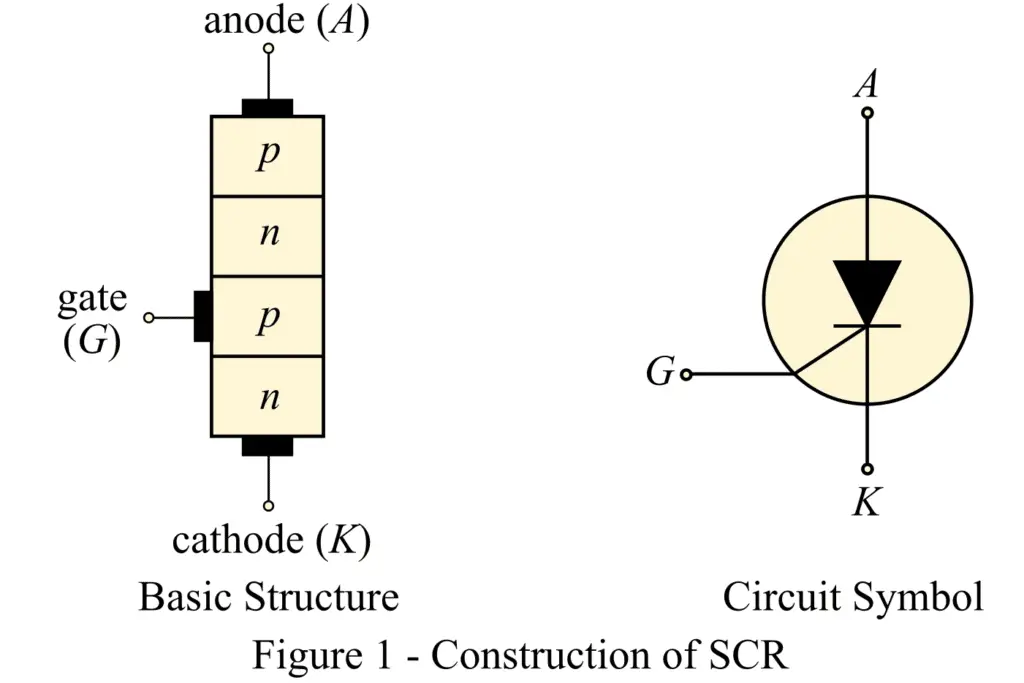
A silicon-controlled rectifier or SCR consists of four layers of semiconductor materials stacked alternatively as shown in figure-1. Therefore, SCR has three pn-junctions. Due to its construction, it is also called a pnpn device. The terminals of SCR are taken as follows:
- Anode (A) is taken from the outer p-type semiconductor layer.
- Cathode (K) is taken from the outer n-type semiconductor layer.
- Gate (G) is taken from the inner p-type semiconductor layer.
The basic structure and circuit symbol of the silicon-controlled rectifier is shown in the figure-1.
Working of Silicon Controlled Rectifier(SCR)
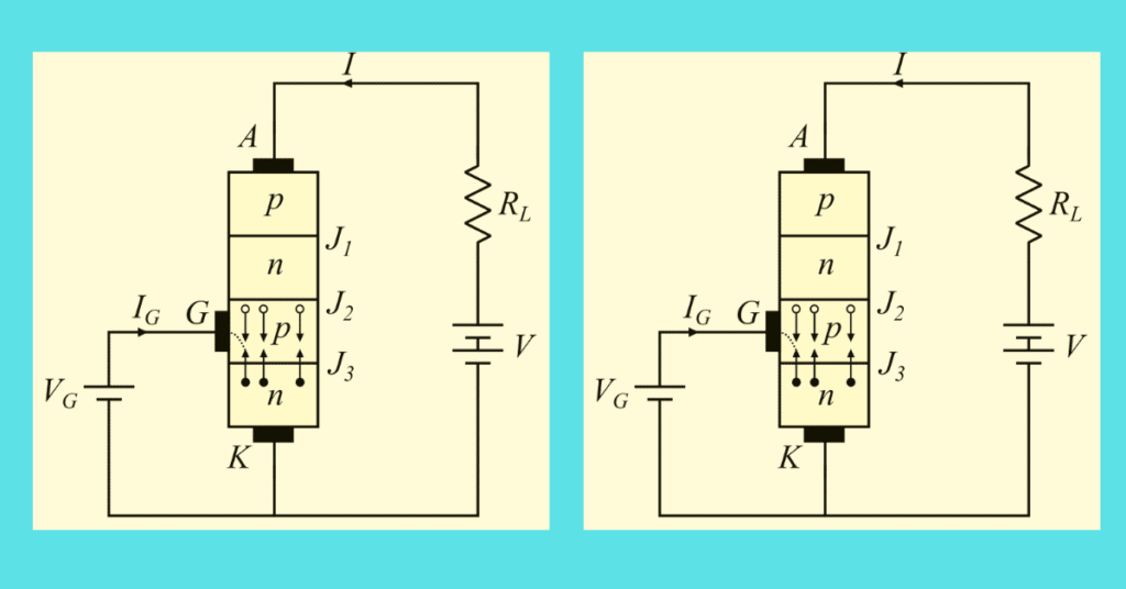
In normal operating conditions, the anode terminal of SCR is connected to the positive terminal, while the cathode terminal is to the negative terminal of the battery. The gate terminal is held a small positive potential with respect to the cathode. The load is always connected in series with the anode terminal of SCR. The complete operation of SCR can be explained in the following two cases:
Case 1 – With open gate terminal
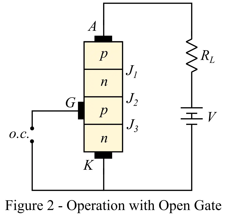
The circuit diagram of SCR with open the gate terminal is shown in figure-2. In this case, no voltage is applied at the gate terminal of SCR. Under this condition, pn-junctions J1 and J2 are forward-biased, while junction J2 is reverse-biased. Due to reverse biased junction J2, no current flows through the device and hence the load. In this condition, SCR is said to be in the OFF state.
Although, if we gradually increase the voltage between the anode and cathode terminals, a stage is reached when reversed junction J2 breaks down, and a large current starts flowing through the SCR and load. Hence, the SCR is said to be in the ON state at this stage. The voltage at which the breakdown of reversed biased junction J2 occurs is called break-over voltage.
Case 2 – Gate Terminal is Positive with Respect to Cathode
We can turn on the SCR at a smaller anode to cathode voltage just by applying a small positive voltage at the gate terminal as shown in figure-3.
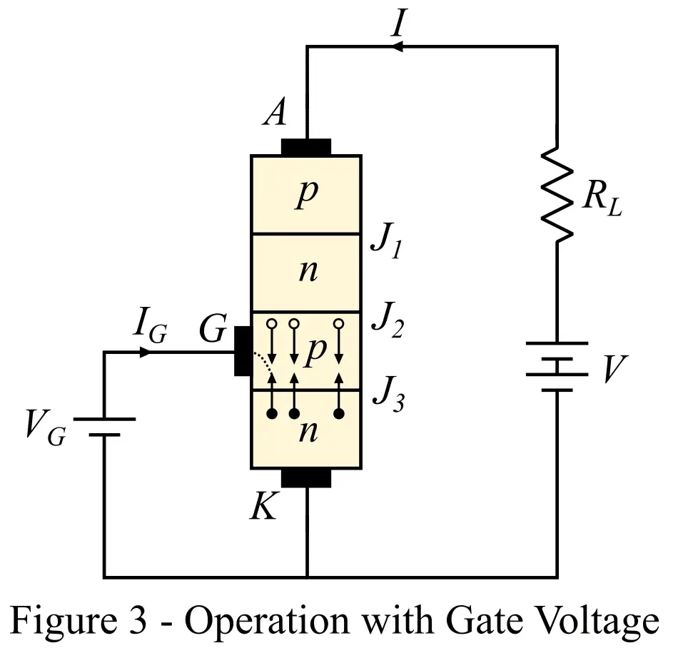
Under this condition, junction J2 is reverse biased while junction J3 is forward biased. Electrons from the outer n-layer start crossing the junction J3 towards the left, and holes from the inner p-layer start moving across the junction J3 towards the right. As a result, a gate current starts flowing.
With the flow of the gate current, the anode current increases. The increased anode current accumulates more electrons at junction J2, and as a result, junction J2 breaks down at a smaller anode-to-cathode voltage. The SCR is turned ON. However, once the SCR starts conducting, the gate circuit loses its control over the operation of the device, which means the SCR will remain in the conduction state even if the gate voltage is removed.
Applications of SCR
SCR is one of the most widely used power semiconductor devices in industrial applications. Some major applications of the silicon-controlled rectifier (SCR) are listed below:
- A silicon control rectifier (SCR) is used to realize a controlled rectifier circuit.
- It is used in AC voltage stabilizers.
- A silicon control rectifier (SCR) is used as an electronic switch for switching high-power industrial loads.
- A silicon control rectifier (SCR) is also used in power inverters.
- SCR is used in the battery charging circuit.
- A silicon control rectifier (SCR) is used to control the speed of induction motors.
- A silicon control rectifier (SCR) is also used in chopper circuits.
- It is used in light dimmer