The V-I characteristics of SCR play a crucial role in power electronics where SCRs are widely used to control large amounts of power. The SCR characteristics—such as its ability to conduct in one direction and its three-mode operation—make it suitable for switching and rectification.
What is SCR?
SCR is a silicon control rectifier that belongs to the thyristor family. The SCR is a four-layer, three-terminal unidirectional semiconductor device that allows current to flow in one direction only.
The three terminals of the SCR are anode, cathode, and gate. The SCR can be turned on by applying the trigger pulse to the gate terminal.

Key Characteristics of SCR
The SCR (Silicon Controlled Rectifier) is a versatile semiconductor device used in power control and switching applications. Below are the key characteristics of SCR:
- Unidirectional Conduction: The SCR allows current to flow only in one direction—from anode to cathode—when properly triggered.
- Three-Terminal Device: It has three terminals—Anode, Cathode, and Gate—for controlled operation.
- Latching Behavior: Once turned on with a gate pulse, the SCR remains in the conducting state even if the gate signal is removed.
- High Voltage and Current Handling: SCRs are available in a wide range of voltage and current ratings, making them suitable for high-power applications.
- Controlled Switching: The gate terminal enables precise control over when the device starts conducting.
- Three Modes of Operation: It operates in Forward Blocking, Forward Conduction, and Reverse Blocking modes.
- Sensitive to Gate Triggering: A small gate current can initiate conduction, allowing for low-power control of high-power circuits.
- Thermal and Surge Limits: SCRs have defined ratings for peak reverse voltage, latching current, holding current, and surge current (I²t rating).
Voltage-ampere(V-I) Characteristics of SCR
The mode of VI characteristics of SCR are as follows.
- Forward Blocking Mode
- Forward Conduction Mode
- Reverse Blocking Mode
The following table summarizes these modes based on the biasing conditions and gate current:
Modes of SCR Operation
| Mode | Anode-Cathode Bias | Gate Current | Condition |
| Forward Blocking | Forward | 0 | J2 reverse biased; SCR is OFF and offers high resistance |
| Forward Conduction | Forward | Present | All junctions forward biased; SCR turns ON and conducts |
| Reverse Blocking | Reverse | Irrelevant | J1 and J3 reverse biased; SCR is OFF and blocks current |
Forward Blocking Mode of SCR
In the forward blocking mode, SCR remains in forwarding bias, but SCR does not conduct. When the anode voltage is positive with respect to the cathode and the gate current is zero, the device remains in the off state.
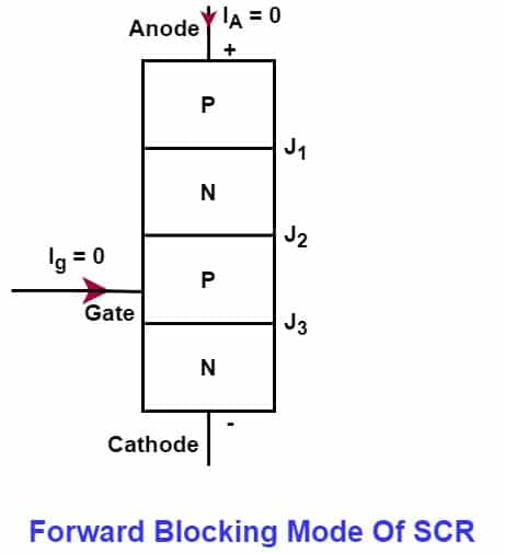
In the forward blocking mode,
- J1 and J3 junction is in forward bias
- J2 junction is in reverse bias
- Very low leakage current flows through the device.
- SCR offers very high resistance.
- SCR remains in an off-state
However, we can turn on SCR by applying a high voltage between the anode and cathode, even if the gate current is zero. The voltage at which the SCR turns on when the gate current is zero is the forward break-over voltage.

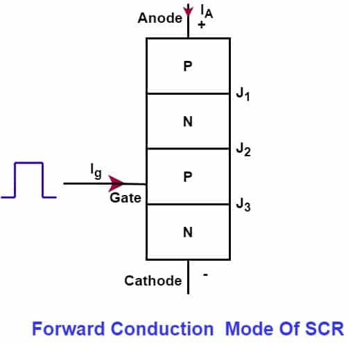
Forward Conduction Mode of SCR
In forward conduction mode, we can turn on SCR at the lower anode-to-cathode voltage by momentarily applying a small gate voltage. The voltage causes the gate current to flow.
Thus, the gate current pulse is sufficient to switch on the SCR at the lower anode-to-cathode voltage. The SCR remains on after the gate current pulse is removed.
The circuit diagram for getting the forward conduction characteristics of the SCR is given below.
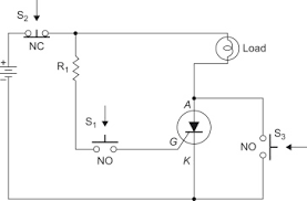
Now, on the application of gate current through switch S1, the J2 junction of SCR starts conducting, and SCR is in forwarding bias.
Thus, all three junctions(J1, J2, and J3) of SCR are now in forwarding bias and it remains in its on state even after the gate current pulse is removed. The SCR offers very low resistance in forwarding conduction mode.
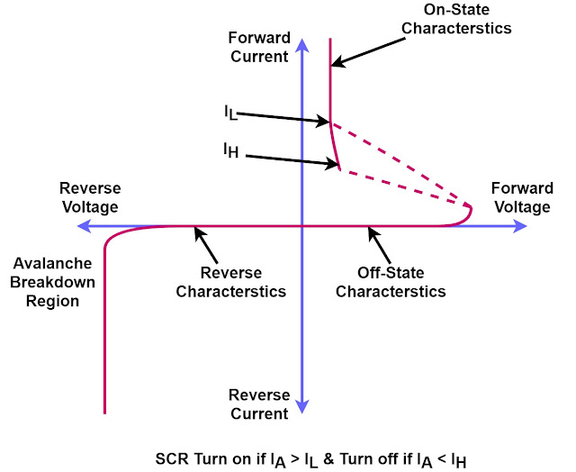
The figure below shows the forward conduction, forward blocking, and reverse blocking regions of the SCR.

The device will remain in the on-state even after removing the gate pulse if the anode current is more than the latching current.
When the anode current reduces below the holding current, the device turns off. The holding current is associated with the turn-off mechanism of SCR. The latching current is always more than the holding current.
The device will remain in the on-state even after removing the gate pulse if the anode current is more than the latching current.
Reverse Blocking Mode of SCR
When we connect the SCR in reverse bias- when the anode is negative with respect to the cathode- the device remains in an off state because junctions J1 and J3 are in reverse bias while junction J2 is forward bias.
The SCR acts as two diodes connected series with a reverse bias applied across it. The device offers very high resistance.
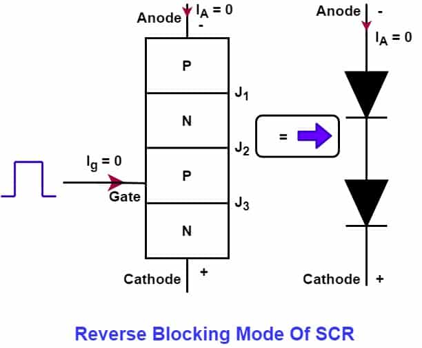
The SCR can be turned on if the voltage across the anode and cathode exceeds the device’s reverse breakdown voltage.
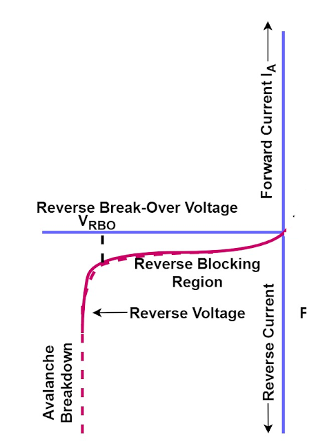
The maximum reverse voltage at which the SCR starts conducting heavily is known as the reverse break-over voltage.
Important Terms in the V-I Characteristics of SCR
We use the following terms frequently while studying the V-I characteristics of the SCR.
- Forward Brekover Voltage
- Latching current
- Holding current
- Forward anode current rating
- Peak reverse voltage
- Circuit fusing rating
1. Forward Breakover Voltage
The minimum forward voltage at which SCR starts conducting in the absence of the gate current. This minimum voltage is the forward break-over voltage of SCR.
For example, the SCR of forwarding break over voltage rating 500 volts remains in its off state when the voltage is below 500 volts, and it starts conducting when the voltage is equal to or above 500 volts.
2. Latching Current
The latching current is the minimum anode current at SCR that remains in its on-state after removing the gate current. If the anode current is less than the latching current, the SCR will not conduct.
3. Holding Current
It is the maximum anode current at which SCR turns off from its on-state. If the holding current is 10 mA, the SCR will turn off if the anode current is less than 10 mA.
3. Peak Reverse Voltage
The peak reverse voltage is the maximum reverse voltage across SCR (cathode-positive and anode-negative) that can be safely applied without conducting the SCR.
This is a very important parameter. when SCR is used for controlled rectification, the reverse voltage applies during the negative half cycle, and SCR must remain in its off state.
The peak reverse voltage of SCR should always be more than the peak negative voltage of AC voltage.
4. Forward Current Rating
The maximum anode current can flow through the SCR without damaging it. The SCR is available in different anode current ratings. A 50 ampere forward current rating SCR can carry 50 amps. current safely.
If the current exceeds the SCR anode’s current rating, the device may fail. Semiconductor devices are vulnerable to temperature.
Therefore, they must be selected according to the required current rating and surrounding ambient temperature.
5. Circuit Fusing Rating
The circuit fusing rating indicates the maximum forward surge current capability of SCR. The circuit fusing rating depends on the current and time.
The fusing rating of SCR is I2t. The heating of SCR must be below the rated fusing rating for reliable SCR operation.
Conclusion
Understanding the V-I characteristics of SCR is essential for designing and analyzing power control circuits.
The three distinct modes—forward blocking, forward conduction, and reverse blocking—define how an SCR behaves under different voltage and gate current conditions.
Parameters like forward breakover voltage, latching current, and holding current help in selecting the right SCR for specific applications.
With its controlled switching ability and high power handling capability, the SCR remains a fundamental component in power electronics.
Related Articles:
Usefull