Definition- The firing angle of an SCR (Silicon Controlled Rectifier) is the angle (in degrees or radians) at which the gate signal is applied to the SCR to turn it on during each AC cycle. This angle is measured from the zero-crossing point of the AC voltage waveform.
Thus, the firing angle of an SCR is the angle after which the thyristor conducts during each AC cycle. By controlling the firing angle, you can control the time the SCR conducts current within each AC cycle, thereby regulating the output voltage and power delivered to the load.
Power electronic devices or switches in control applications are known for their efficient working and less power consumption compared to traditional methods, where we used rheostats or shunts to control voltage or current-dependent parameters. One such power electronics device is an SCR or Silicon Controlled Rectifier.
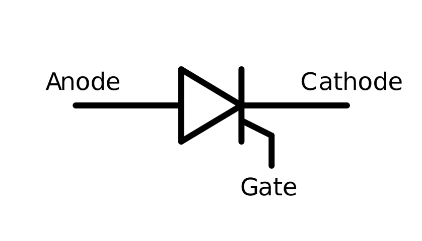
Silicon-controlled rectifier (SCR), also known as Thyristor, is a three-terminal semiconductor device used in various applications, such as motor speed control. The three terminals are ANODE, CATHODE, and GATE, as shown below.
The device’s working principle is the same as that of a P-N junction diode. The only difference is the availability of a GATE terminal in the SCR, which must be supplied for the SCR to conduct. The gate terminal is provided with adequate voltage at a particular moment in time, which, in angular terms, is referred to as the firing angle. Let’s understand the firing angle in detail.
Firing angle in an SCR
Let’s consider an electrical load with an AC supply connected in series with a P-N junction diode. As a result, the forward-biased diode will conduct for the entire positive half of a cycle while it will be reverse-biased for the negative half and will stop conduction. Thus, the load will receive power only during the positive half of the AC supply. In this way, the diode rectifies the input AC to DC.
The SCR or Thyristor works on the same principle except that even after being forward-biased, it can conduct when the gate terminal is supplied with an appropriate voltage.
Thus, the SCR remains forward-biased for the positive half cycle of the AC supply. At a particular instant, the gate terminal is supplied, which causes the SCR to conduct.
The advantage of SCR control is that while we have no control over the average voltage output from the diode as it conducts for the complete half cycle, with SCR, we can control the output voltage by supplying the gate terminal at an appropriate instant within the positive half cycle.
This supply of the gate current to the gate terminal is known as the gate-firing of the SCR, and the instant at which the gate is fired is known as the firing angle.
The term ‘angle’ denotes the angle at which the AC waveform at an instant of time. Let’s understand the SCR firing angle with the help of a mathematical model.
Mathematical analysis of firing angle
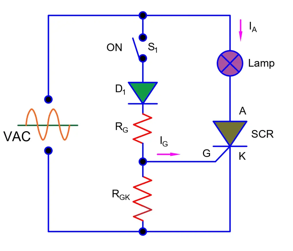
The circuit diagram depicted above shows a load connected to an AC supply via an SCR. In this setup, the load is represented by a lamp. During the positive half cycle of the AC supply, the SCR becomes forward-biased because the anode (A) is connected to the positive voltage terminal, and the cathode (K) is connected to the negative voltage terminal.
Even though the SCR is forward-biased, it doesn’t allow conduction as its gate terminal has not been supplied. To allow conduction through the SCR, switch S1 is closed, thus allowing a suitable current to flow to the gate terminal. RG and RGk are the gate voltage limiting resistors, as the voltage required for triggering (i.e., activating or supplying) the gate terminal is very small. The diode D1 ensures a positive trigger voltage appears at the gate terminal.
Now, at a particular instant of time, let’s say t1, the switch S1 is closed, and thus, the SCR begins to conduct. The SCR will, therefore, keep on conducting for the duration from instant t1 until the end of the positive half cycle. The figure given below shows the source AC voltage. The shaded region within the positive half cycles represents the duration for which the SCR is conducted.
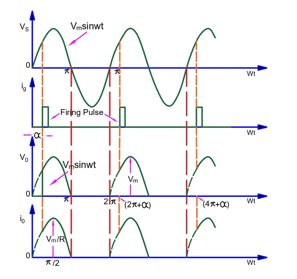
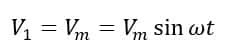
The instantaneous voltage of the source is given as
The firing angle is denoted by α, as shown in the waveform. This firing angle is the angular representation of the instant at which the SCR gate is triggered, i.e., t1.
Now, let us put all these things in perspective. Let’s say I want to activate the circuit at the instantaneous voltage V1. So, we need to calculate the required firing angle corresponding to this voltage.
Therefore,
Where α is the firing angle at the instant when the instantaneous voltage reaches V1. So, the firing angle α will be ;
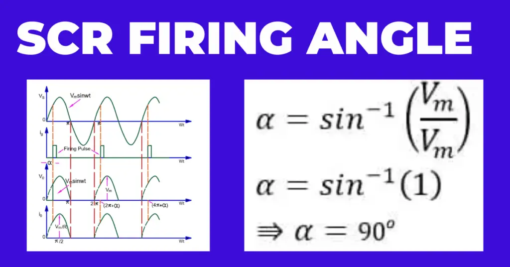
Let’s understand this all with the help of an example. Let’s assume the SCR in the above-given circuit starts conducting when the instantaneous voltage reaches its maximum value. What will be the firing angle? Let’s calculate
So, in this scenario
Therefore, the firing angle is
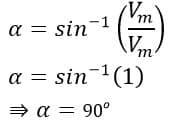
Therefore, the firing angle to activate the SCR at maximum source voltage is 90 degrees. But how are we going to use this angle in the circuit? For that, we have to know the time instant at which the voltage waveform reaches 90 degrees, i.e., the point of maximum voltage.
Therefore, we put a 90-degree value in the equation of source instantaneous voltage to obtain the corresponding time instant.
So,
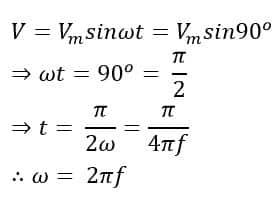
Therefore,
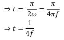
Assuming the source voltage frequency, f = 50Hz or 50 cycles/sec., we get
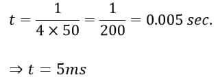
Thus, to allow the SCR to start conduction at peak or maximum voltage, we must trigger it at a firing angle of 90 degrees. To do that, we have to close the gate trigger switch S1 (in the circuit given above) after five milliseconds each time in the positive half-cycle of the voltage waveform.
However, this switching is not done physically as it is not possible to trigger the gate terminal within 5ms physically. Thus, a triggering circuit like an RC circuit is employed, which can generate a positive pulse every 5ms as the source voltage waveform enters its positive half-cycle.
During the negative half-cycle, the SCR remains reverse-biased and doesn’t conduct even if the gate is triggered.
Calculation of load voltage for the Given firing angle of the SCR
Now, you must be wondering what the advantage of all this is. What purpose does the firing of the SCR serve? The answer is smooth and efficient voltage control.
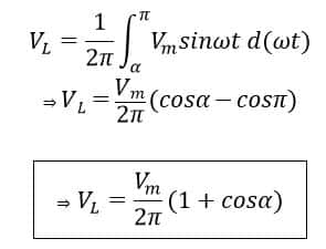
Now, in the waveform given above, the SCR starts conducting at the firing angle ωt= α and continues to conduct till ωt= π for one complete cycle from 0 to 2 π. Therefore, the average load voltage is ;
Thus, by knowing the value of the firing angle, we can calculate the average load voltage. For example, α = 900 and Vm= 220 X√2, assuming the RMS voltage is 220V. So, the average load voltage is;
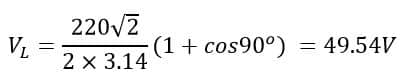
Thus, we have efficiently controlled the voltage for the load to 49.54V. While this can be done using resistors as well that would lead to enormous power loss across the resistor. Whereas in the case of SCR, the voltage drop is very small across it (0.7~1V). This is the advantage of using an SCR.
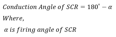
How much time does the SCR remain in the conduction State?
The time during which an SCR remains in the conduction state within each AC cycle depends on the firing angle (α). Once the SCR is triggered (i.e., the gate signal is applied), it remains in conduction until the current through it drops to zero. In an AC circuit, this typically occurs at the end of each half-cycle of the AC waveform. The angle during which the SCR is in the conducting state within each AC half-cycle is called the conduction angle of an SCR. This conduction angle is complementary to the firing angle