A Single phase half wave rectifier converts AC voltage to DC voltage. It requires only one diode for rectification.
What is Rectifier?
The rectifier is the device that converts alternating current(AC) into direct current(DC). The alternating current periodically reverses its direction, whereas the direct current does not periodically change its direction.
What is a Half-Wave Rectifier?
The half-wave rectifier passes one half-cycle of the alternating current and blocks the other half-cycle. Thus, in one complete cycle of the AC waveform, the half-cycle is passed. In a half-wave rectifier, only one diode is used to convert AC into DC.
Single Phase Half Wave Rectifier Theory
Now, we will discuss the theory of a single-phase half-wave rectifier.
How does Single Phase Half-Wave Rectifier functions?
The main part of the half-wave rectifier is the diode. The diode conducts if the anode voltage is more than the cut-in voltage of the diode. The cut-in voltage of silicon and germanium diodes is 0.7 and 0.3 volts, respectively. If the anode voltage is more than 0.7 volts, the diode starts conducting. In power electronics, silicon diodes are generally used because they have a low forward resistance, which makes them suitable for delivering high forward currents.
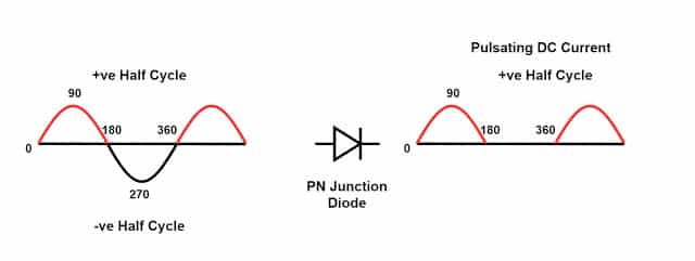
During one positive half cycle, the diode conducts and passes the waveform for the period from o to π. The diode does not conduct for the period from π to 2π because the anode potential is less than the cut-in voltage of the diode. The output waveform of the diode is the DC voltage since it has positive pulses. The output DC waveform has more ripples, and it is not smooth.
We can get negative DC voltage by making the diode conduct during the negative half cycle of the AC waveform.
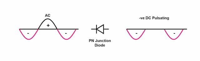
The diode conducts during the negative half cycle of the AC waveform. During the positive half cycle, the diode is in reverse bias, and no current flows through the diode.
Circuit Diagram of Half Wave Rectifier
The circuit diagram of the half-wave rectifier is shown below.
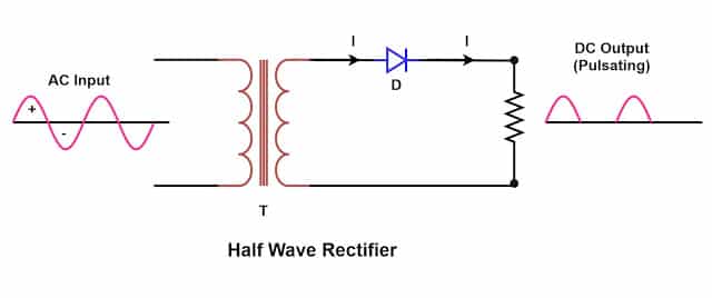
The half-wave rectifier circuit consists of three main parts.
- Transformer
- Diode
- Resistive Load
The voltage is applied at the primary side of the transformer. The low voltage is induced in the secondary of the transformer according to the transformer’s turns ratio. The voltage is reduced to get the desired DC voltage. The simplified equivalent secondary circuit of the rectifier is as given below.
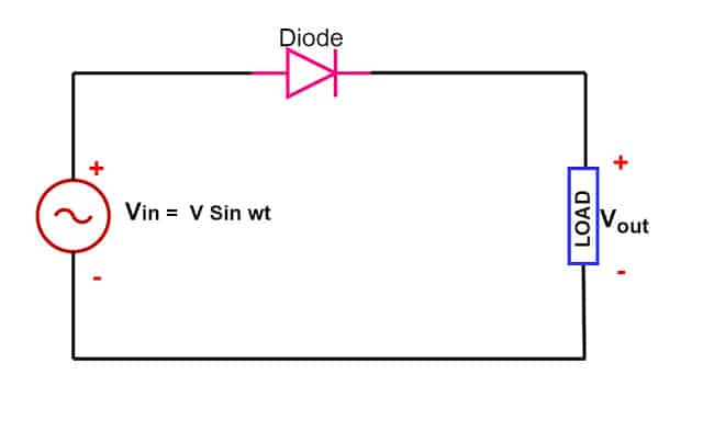
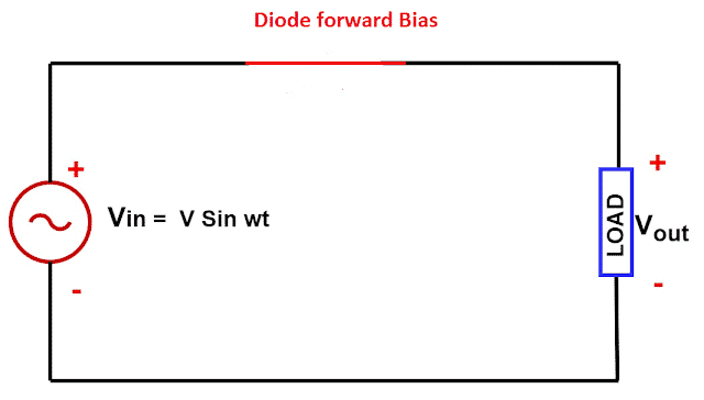
During the positive half cycle of the AC waveform, the voltage at the anode of the diode is more than its cut-in voltage, and the diode becomes forward-biased and starts conducting. Thus, in the positive half cycle, the diode remains in the conducting state, and current flows through the diode. The diode has very low forward resistance during its forward biasing state, and the diode behaves as a short circuit, considering zero forward resistance.
The diode stops conducting when the AC waveform crosses zero and goes towards the negative half cycle. During the negative half cycle, the diode is in reversed bias, and no current flows through the diode. During the negative half cycle, the diode is an open circuit. The half-wave rectifier equivalent circuit is given below.
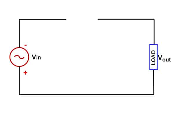
During the negative half cycle, the diode’s reverse resistance is very high, acting as an open circuit and preventing current from passing through it.
Single Phase Half Wave Rectifier Formulas
We will discuss how the various formulas of half-wave rectifiers are used for assessing the rectifier performance.
Average value or DC value of Single Phase Half Wave Rectifier
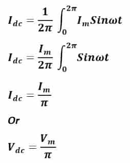
We can calculate the average or effective DC output of a half-wave rectifier by taking the average of the DC output voltage. The instantaneous value of current at the output of the rectifier is i=ImSinωt. The average load current across the load resistance is equal to:
RMS Value of Single Phase Half Wave Rectifier
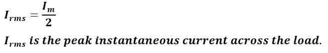
For a half-wave rectifier, the RMS load current (Irms) is equal to the average current (IDC) multiple by π/2. Hence, the RMS value of the load current (Irms) for a half-wave rectifier is:
Ripple Factor of Single Phase Half Wave Rectifier
The ripple factor shows the effectiveness of rectification. The output of the rectified DC also has an AC component. The AC component is undesirable in the rectified DC output, and the AC component available in the rectified DC is ripple. It is practically impossible to eliminate the AC component in the rectified DC output. However, the lesser ripples in the rectified waveform make the output DC smoother.
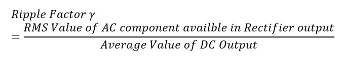
The ripple factor is the ratio of the AC components available in the rectifier output to the average value of the DC output.
We can express the ripple factor of the half-wave rectifier by the following mathematical expression.
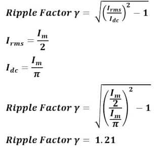
The ripple factor of the half-wave rectifier is 1.21. It is possible to lower the ripples by the installation of a capacitor and inductor as a filter circuit.
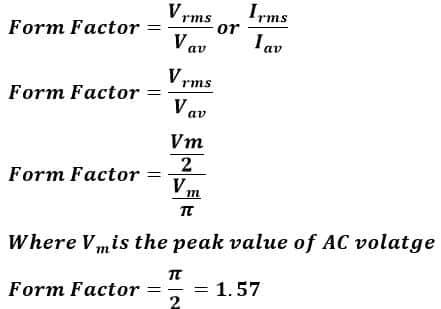
Form Factor
The ratio of the RMS value and the average value is the form factor.
Efficiency of Half Wave Rectifier
The ratio of output DC power to the input AC power is the rectifier efficiency. The formula for the efficiency is equal to:
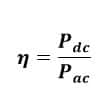
The efficiency of the half-wave rectifier is equal to 40.6%.
Peak Inverse Voltage of Half Wave Rectifier
The peak inverse voltage of the diode is the maximum voltage that a diode can withstand during reverse bias conditions. If the diode’s voltage is above the peak inverse voltage(PIV), it is apt to fail.
Half Wave Diode Rectifier Applications
- Power rectification: We use a half-wave rectifier for rectification of AC to get DC Voltage.
- Signal demodulation: With demodulation, the original signal sent from the transmitter end can be recovered. A half-wave rectifier is the best choice for demodulating modulated signals.
- Signal peak detector: The simple half-wave diode detector can detect the peak value of a waveform. Therefore, we use it as a peak detector.
Advantages of Half Wave Rectifier
The half-wave rectifier is very simple to construct. The half-wave rectifier has a very small number of components.
- The lower number of components
- Cheaper
Disadvantages of Half Wave Rectifier
The disadvantages of the half-wave rectifier are :
- It rectifies only half of the AC wave and filters the other half-cycle. Therefore, its efficiency is very low about (40%).
- The output DC voltage is low.
- The output DC contains more ripples; thus, the output is not purely DC.
Solved Problems on Single Phase Half wave Rectifier
Example No. 1
The applied input power to a half-wave rectifier is 200 watts. The DC power output of the rectifier is 80 Watts. What is the efficiency of the rectifier?
Rectification efficiency = Pout/Pin x 100
= 80/200 x100
= 40 %
Example No. 2
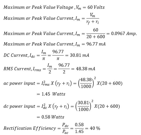
An ac supply v= 60 Sin ωt is applied to a half-wave rectifier. The internal resistance of the diode(rf)is 20 Ω, and the load resistance is 600 Ω. Calculate – (1) Ac Power Input (2) DC power Output (3) Efficiency of rectification.
Example No. 3
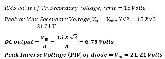
An ac supply of 230 volts is applied to a step-down transformer of 230/15 volts, whose secondary is connected to the half-wave rectifier.
Find
(1) The output DC Voltage
(2) PIV of diode.
Thanks for this write-up. It’s very educative.
Yes this one was a very nice explanation. Go ahead and make other more exciting scientific stuff explained so nicely like this. Hare Krsna.