When designing the electrical layout for a large industrial facility, a data center, or a massive commercial complex, engineers face a major challenge: how to move immense amounts of electrical power safely and efficiently. The traditional answer has always been heavy, thick bundles of cable pulled through rigid metal pipes called conduit. However, there is a far more efficient, space-saving, and adaptable alternative that heavy industries have relied on for nearly a century: the bus duct.
First introduced to the automotive industry back in 1932 to streamline rapidly changing assembly lines, bus duct systems (also widely known as busways) have grown to become the standard choice for modern power distribution across many sectors worldwide.
What is a Bus Duct?
At its core, a bus duct is a pre-fabricated, grounded sheet metal enclosure that houses solid metallic strips called busbars. These internal conductors are typically made of high-conductivity copper or aluminum, and they are designed to carry substantial electrical currents safely and efficiently.
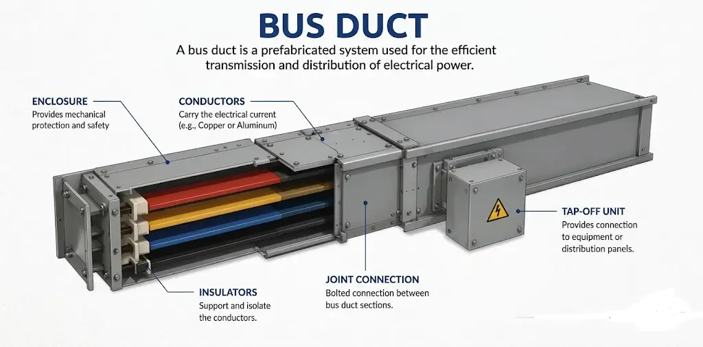
A bus duct can be thought of as a modular electrical highway designed for high-current power transmission. Instead of spending days pulling miles of individual cables through tight spaces, installation teams can quickly bolt together pre-engineered sections of busway. This creates a highly reliable link that transfers power from one major piece of equipment to another at the exact voltage levels required.
Cable vs. Bus Duct: When to Make the Switch
There is a common misconception in the industry that a bus duct is only practical or cost-effective for massive, high-amperage industrial applications. In reality, modern busway systems provide a high degree of efficiency across the entire power spectrum, ranging from approximately 100 A to over 6,500 A.
- Low-Amperage Flexibility: High-tech facilities, such as computer manufacturers, data centers, and laboratories, frequently use low-amperage busway designs. The primary benefit here is future flexibility. Thanks to specialized plug-in tap-off openings, maintenance teams can easily attach “tap-off” units to power new rows of equipment. This allows for quick layout changes without shutting down the entire electrical grid or running brand-new lines. This modular design also simplifies future maintenance, upgrades, and system expansion.
- High-Amperage Muscle: Heavy assembly industries, like automotive plants and steel mills, demand immense continuous current. High-amperage busway designs handle these severe loads with ease. They take up a fraction of the physical space required by traditional cable trays and dramatically reduce voltage drop (ΔV) over long distances due to their lower inductive reactance.
- Layout Versatility: Because modern facilities are complex, busway systems are highly versatile. Manufacturers offer a wide array of matching components like modular elbows, offsets, and T-connections. These parts allow the duct to easily navigate tight corners and sudden changes in direction.
- Better Heat Dissipation: Compared to tightly bundled cables, bus ducts generally provide superior heat dissipation due to their metallic enclosure and spaced conductor arrangement. This improved cooling capability helps reduce overheating risks and improves overall system efficiency, especially in high-current applications.
Types of Bus Duct: Segregated vs. Non-Segregated
To ensure total system reliability and safety, busways are engineered differently depending on the voltage level and the environment. They are primarily split into two main design categories:
1. Non-Segregated Phase Bus Duct (Low Voltage)
In a non-segregated busway, all the phase and neutral conductors run together inside a single, shared metal enclosure. As the name implies, there are no physical metal walls or barriers separating the bars from one another. Instead, the system relies on carefully calculated air gaps and busbar insulation sleeves to act as the natural insulation medium between the phases.
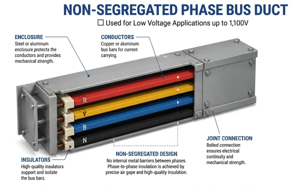
Because these are used for low-voltage applications (typically up to 1,100 V), they require much smaller electrical clearances. This makes the entire duct incredibly compact and cost-effective. They are widely used to connect low-voltage diesel generators to switchgears, or to route main power inside commercial buildings. To reduce voltage drop even further, manufacturers often use an “interleaved” layout design that balances the internal magnetic fields and minimizes proximity effects.
2. Segregated Phase Bus Duct (Medium Voltage)
When dealing with medium-voltage power systems (ranging from 3.3 kV up to 33 kV), the physical forces and safety risks increase dramatically. In a segregated phase bus duct, all three phase bars are still enclosed within one main outer casing, but they are physically separated from one another by internal metal walls.
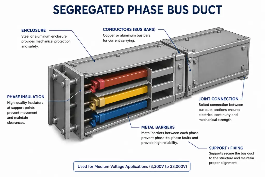
These metal barriers are typically welded directly to the outer enclosure, creating a separate, shielded compartment for every single phase. This design choice does two critical things:
- Fault Minimization: It almost completely eliminates the risk of a dangerous phase-to-phase short circuit.
- Magnetic Shielding: During a sudden short circuit, massive magnetic forces can physically twist or warp heavy metal bars. The internal barriers generate an opposing magnetic effect that helps absorb these destructive physical forces.
Because of this heavy-duty protection, segregated busways are the standard choice for major industrial interconnections, such as linking main outdoor power transformers to indoor switchgear lineups.
Summary Comparison: Segregated vs. Non-Segregated Bus Duct
| Feature | Non-Segregated Phase | Segregated Phase |
| Voltage Level | Low Voltage (Up to 1,100 V) | Medium Voltage (3.3 kV to 33 kV) |
| Internal Barriers | None (Uses precise air gaps) | Metal barriers between each phase |
| Main Benefit | Highly compact and budget-friendly | Prevents dangerous phase-to-phase shorts |
| Common Use | Linking low-voltage generators to panels | Connecting major power transformers to switchgear |
Conclusion
While traditional cable and conduit systems still have their place in smaller and permanent installations, bus ducts offer major advantages in space savings, scalability, safety, heat dissipation, and maintenance flexibility. By replacing bulky cable bundles with a clean, modular power distribution system, modern facilities can build electrical infrastructure that is safer, more efficient, and easier to expand as power demands grow.
Read Next: