An LDR datasheet is the essential technical document used to evaluate a Light Dependent Resistor (also known as a photoresistor or photoconductive cell), which is a passive component whose resistance decreases as the intensity of incident light increases. In industrial automation, street lighting controls, and basic optoelectronic circuits, understanding these manufacturer specifications allows engineers to use the LDR as a cost-effective and highly reliable component for ambient light sensing.
However, selecting or replacing an LDR sensor requires a precise understanding of its technical parameters. This article provides a comprehensive breakdown of an LDR datasheet, detailing electrical specifications, material characteristics, and practical circuit design considerations.
What is an LDR Datasheet?
An LDR datasheet is a technical document provided by manufacturers (such as Advanced Photonics, Lunoptik, or generic series like the GL55xx) that outlines the electrical, thermal, and optical performance limits of a photoresistor. Unlike standard fixed resistors, an LDR is a non-linear device whose behavior depends heavily on environmental variables like ambient light intensity and operating temperature.
Core Technical Parameters in an LDR Datasheet
When analyzing an LDR sensor datasheet, designers must evaluate several critical parameters to ensure circuit stability and prevent component degradation.
Light Resistance (R10 or RL)
This parameter represents the resistance value of the component under a standardized light intensity—typically 10 Lux (using a standard CIE light source ‘A’ tungsten lamp at a color temperature of 2856 Kelvin). A standard GL5528 LDR sensor datasheet usually specifies a light resistance range between 10 kΩ and 20 kΩ.
Dark Resistance (Rd)
This is the resistance value when the sensor is completely shielded from light (0 Lux). For a high-quality photoresistor, the dark resistance should be as high as possible to minimize leakage current. Most LDR datasheets specify a minimum dark resistance of 1 MΩ to 10 MΩ.
Gamma Characteristic (γ)
The relationship between light intensity (E, measured in Lux) and resistance (R) is non-linear and logarithmic. The gamma characteristic defines the slope of this curve, calculated using the formula:
Where R10 is the resistance at 10 Lux and R100 is the resistance at 100 Lux. A standard datasheet value for γ ranges from 0.6 to 0.8. A higher gamma value indicates greater sensitivity to changes in light intensity.
Maximum Voltage (Vmax)
The maximum continuous DC or peak AC voltage that can be applied across the LDR leads under dark conditions without causing dielectric breakdown. Typical values range from 100 V to 250 V, depending on the physical size of the ceramic substrate.
Power Dissipation (Pmax)
The maximum allowable power the component can dissipate safely at a standard ambient temperature (25∘C). Exceeding this limit causes thermal runaway, permanently shifting the baseline resistance values. Standard values for 5mm encapsulated LDRs are usually around 100 mW, dropping linearly as temperature rises.
Optical and Thermal Behavior
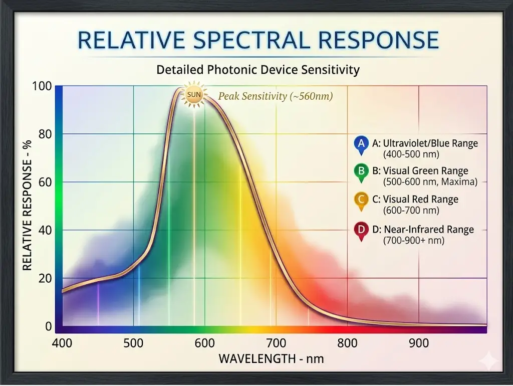
Spectral Response Curve
The chemical composition of the semiconductor material determines the wavelengths of light the LDR responds to. Most commercial photoresistors use Cadmium Sulfide (CdS), which exhibits a peak spectral response at approximately 540 nm to 560 nm. This perfectly mirrors the human eye’s sensitivity curve, making CdS LDRs excellent for lighting systems designed around human perception.
Response Time (Rise and Fall Time)
LDRs are fundamentally slow devices compared to photodiodes or phototransistors.
- Rise Time (Tr): The time required for the resistance to drop to its final value when light is applied. Typically 20 ms to 30 ms.
- Fall Time (Tf): The time required for the resistance to recover to its baseline dark state when light is removed. Typically 30 ms to 40 ms.
LDR Sensor Model Comparison Table
The table below represents typical reference data extracted from popular standard commercial LDR datasheets:
| Model Number | Light Resistance (at 10 Lux) | Dark Resistance (Min) | Gamma (γ) | Max Voltage (Vmax) | Power Dissipation (Pmax) | Peak Wavelength |
| GL5516 | 5 – 10 kΩ | 0.5 MΩ | 0.6 | 150 V | 90 mW | 540 nm |
| GL5528 | 10 – 20 kΩ | 1.0 MΩ | 0.7 | 150 V | 100 mW | 540 nm |
| GL5537 | 20 – 30 kΩ | 2.0 MΩ | 0.7 | 150 V | 100 mW | 540 nm |
| GL5549 | 45 – 140 kΩ | 10.0 MΩ | 0.8 | 150 V | 100 mW | 540 nm |
Conclusion
The LDR datasheet is an essential resource for hardware designers, engineers, and hobbyists looking to implement reliable light-sensing capabilities in their circuits. By carefully evaluating critical design metrics such as light and dark resistance tolerances, maximum voltage limits, and response lag, you can prevent component failure and optimize the performance of your analog control networks.
Frequently Asked Questions (FAQ)
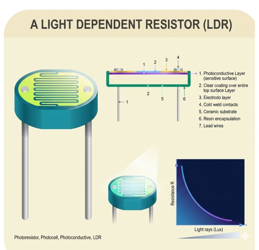
Most commercial LDRs are constructed using Cadmium Sulfide (CdS) or Cadmium Selenide (CdSe). The semiconductor track is deposited onto a ceramic substrate in a zig-zag pattern to maximize the surface area exposed to light while keeping the overall package compact.
Standard Cadmium Sulfide (CdS) LDRs are generally not RoHS compliant because cadmium is a hazardous heavy metal restricted under environmental regulations. Due to this restriction, modern industrial hardware design often substitutes LDRs with RoHS-compliant silicon photodiodes or specialized IC ambient light sensors.
Due to variations in chemical deposition during mass manufacturing, the exact thickness and composition of the photo-sensitive track can vary slightly from unit to unit. Manufacturers provide a tolerance range (e.g., 10-20 kΩ) to assist engineers in planning worst-case scenario voltage divider calculations.
As ambient temperature increases, thermal excitation causes additional free electrons to clear the valence band, lowering the overall baseline resistance independently of light conditions. If operating an LDR in extreme temperatures, a compensation factor must be included in the analog instrumentation loop.
Read Next: