PWM inverter function on the principle of pulse width modulation technique. The PWM inverter can switch on and off the IGBT at much faster rate. Thus, it is possible to get almost perfect sinusoidal voltage, with a very low harmonic distortion.
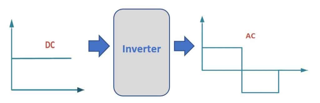
Power Inverter is a power electronics device that converts DC signal into AC signal. It is a static device that transforms power from a dc source (like Battery, PV panel) to the AC load. Unlike an AC generator, the inverter is compact in size.
The primary applications of the power converter are for feeding high current and voltage. The circuit used for the same applications in an electronic circuit (lower current and voltage) is called oscillators. The rectifier performs the reverse action of an inverter.
What is a PWM Inverter?
The invention of rectifiers and inverters was a revolutionary in electrical engineering. Further, the invention of the inverter leads to a new era of power generation from PV panels. Nowadays, the inverter is the key controlling device in power generation. The Inverters are widely used for converting solar PV cell DC voltage into AC voltage. Also, PWM inverters are widely used in variable frequency drives..
PWM stands for pulse width modulation. The width of the pulse is varied maintaining an instantaneous magnitude the same as the input. PWM is a switching technique that controls pulse width by tuning switches between supply and load. The frequency of the switching process is very high therefore it does not affect the load. For this reason, the PWM technique is most suitable for the inertial loads(motor).
PWM technique is superior to the other conventional switching techniques. The advantage of using the PWM technique is that we can vary the magnitude and frequency of the output voltage without increasing the number of stages. Therefore, it is possible to eliminate some of the lower order harmonics and thus, this improves the quality of the output waveform reducing the filtering requirements.
Types of PWM Inverters
The followings are the PWM techniques used in PWM inverters.
- Single pulse width modulation
- Multiple pulse width modulation
- Sinusoidal pulse width modulation
Single Pulse Width Modulation
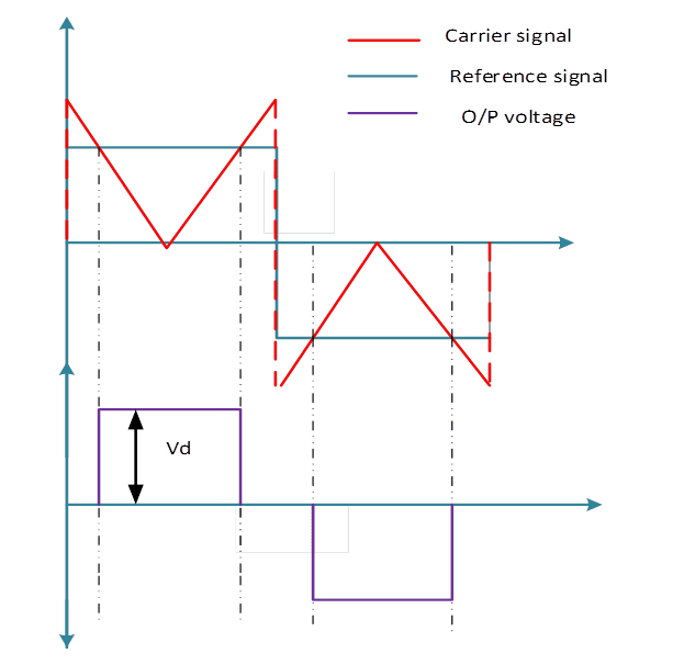
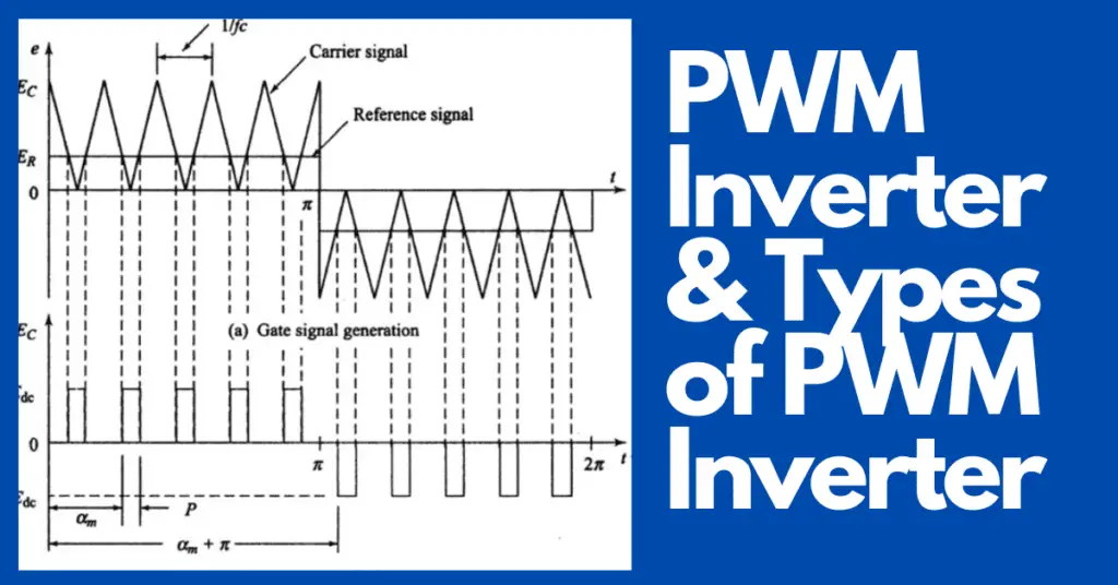
This is a PWM technique in which there is only one pulse present in each half cycle of the output waveform. In this technique, the comparator circuit first compares the carrier and reference signal and outputs the signal for switching of IGBT or power transistor. The frequency of the reference/modulating signal is the deciding factor for the frequency of output voltage.
There are two types of single pulse width modulation techniques depending upon the type of carrier signal.
Type-I
In this type of SPWM(Single Pulse width modulation), the maximum magnitude of the carrier signal coincides with the starting point of the modulating signal. And, the switches get on for the period when Am>Ac.
Type-II
In this type of SPWM maximum magnitude of the carrier signal coincides with the starting point of the modulating signal. and, the switches get on for the period when Am<Ac.
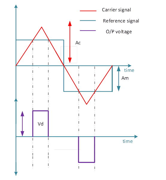
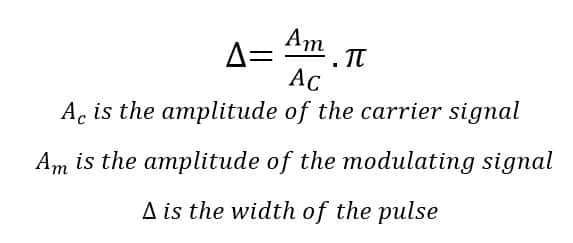
Here, delta (Δ) can be varied by varying the magnitude of the carrier signal or modulating the signal without changing frequency. The ratio of the amplitude of the reference signal to the carrier signal is called the modulation index.
From Fourier analysis of the output voltage waveform, the output voltage is;
Where n is the number of harmonics. The output voltage is free of even order harmonics because of HWS (Half wave symmetry). To eliminate any specific harmonic value can be adjusted to make Sine term zero.
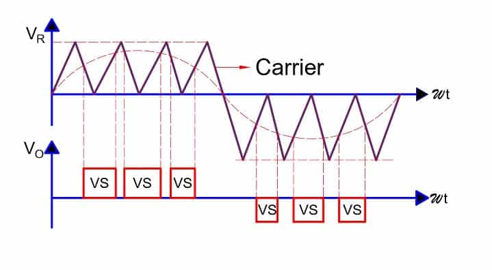
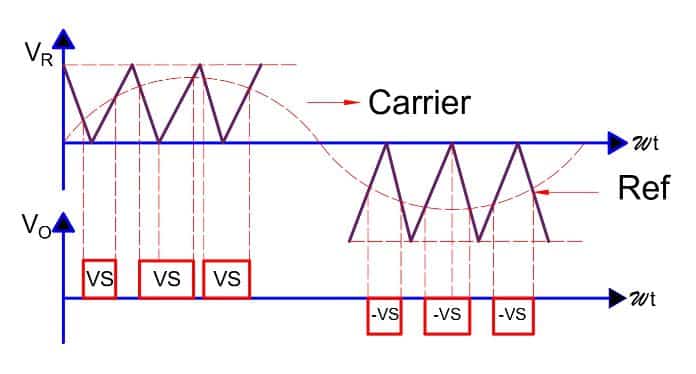
Multiple Pulse Width Modulation
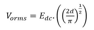
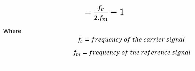
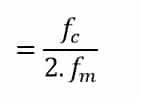
In multiple pulse width modulation, there is more than one pulse present in each half-cycle. The width of each pulse is the same and can be varied by varying amplitude of carrier signal. The frequency of reference signal decides the frequency of the output signal. In this method, harmonics distortion is less in comparison to the previous one. The carrier frequency decides the number of pulses per half cycle.
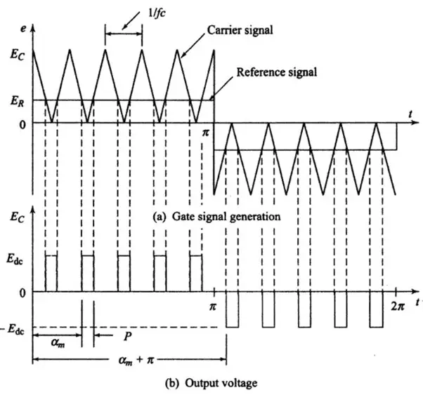
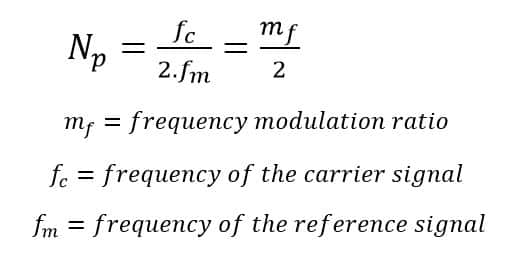
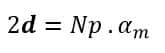
The number of pulses per half cycle is
According to the above-given figure,
The total pulse width per each half cycle is
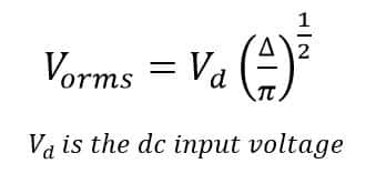
RMS voltage of the output is ;
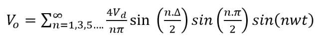
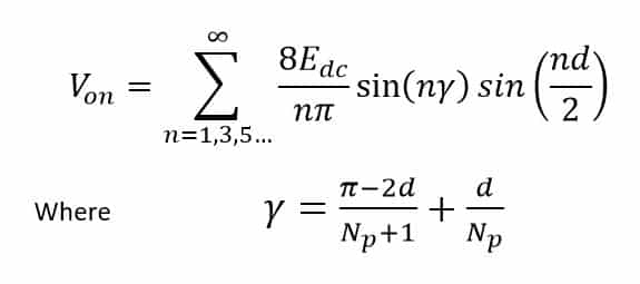
From Fourier representation of output voltage is;
Sinusoidal Pulse Width Modulation
In this type of technique, the sinusoidal signal is the reference signal, and the triangular signal is the carrier signal. The number of pulses increases in each half cycle which improves the quality of output. Therefore, the lower order harmonics decreases. The higher-order harmonics increase, however, we can easily filter out these harmonic orders. There are three types of Sinusoidal PWM techniques.
Type-I
The zero of the carrier coincides with the zero of a reference signal
In the above figure, the sinusoidal signal is a reference signal, and the triangular signal is a carrier signal.
The number of pulses in each half cycle is;
Type-II
The peak of the carrier coincides with the zero of the reference signal
In this case, the number of pulses per half cycle is;
The output voltage is directly proportional to the modulation index(m=Am/Ac)
The output voltage is directly proportional to the modulation index and input dc voltage, RMS voltage can be varied by varying modulation index and the instantaneous voltage can be varied by changing DC input voltage. Thus, the PWM inverter can vary the output voltage and frequency simultaneously.
Type-III
In this type of PWM technique, we maintain the modulation index greater than one, for which AC output voltage remains almost constant. The output waveform looks like a simple square wave. This is also called a case of Overmodulation (m > 1).
Applications of PWM Inverters
- The PWM inverters are widely used in variable frequency drives for controlling the speed of induction motor. The speed of the induction motor is proportional to the frequency. But, one very important point here is that the voltage must increase or decrease on increase/decrease of frequency. The ratio of voltage to frequency(V/f) must be constant to maintain the constant flux in the motor. The PWM inverter simultaneously increase or decrease the frequency and voltage.
- In solar power system, the PWM inverter are most suitable for conversion of solar PV cell DC voltage into AC voltage.
- The PWM inverters have wide application in online and off line uninterrupted power supply(UPS).
Read Next: