In VVVF drive, the V/f ratio is kept constant to maintain the rated flux in the motor. The higher V/f ratio causes the motor’s core to overheat and, eventually damaging the motor.
VVVF (Variable Voltage Variable Frequency) control is used to regulate the speed of an induction motor. The VVVF drive adjusts both voltage and frequency simultaneously, allowing precise and efficient speed control — hence the name Variable Voltage Variable Frequency drive.
What is the Full Form of VVVF?
VVVF stands for “Variable Voltage Variable Frequency”.
Are VFD and VVVF Drive the Same?
Yes, a VVVF drive is another name for a VFD (Variable Frequency Drive).
Both are used to control the speed and torque of AC motors by varying supply voltage and frequency.
Why is V/f Ratio Kept Constant in VFD?
To understand the significance of the V/f ratio, we first need to look at how speed control in an induction motor works.
Speed of Induction Motor
The synchronous speed of an induction motor is given by the formula:
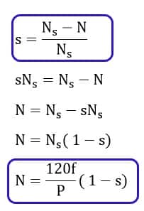
Where,
Ns = 120f/P- The Synchronous speed of the motor
f = Frequency
s = Slip of the motor
P = Number of poles.
Factors Affecting Induction Motor Speed
- Frequency of supply
- Number of poles in stator winding
- Slip, which depends on load
Why Voltage Alone Cannot Control Speed Efficiently
Reducing voltage without reducing frequency lowers the motor’s magnetic flux, resulting in a drop in torque.
This method is only viable for light loads at reduced speeds and leads to inefficient performance under normal conditions.
VVVF Speed Control of Induction Motor
The most effective way to control an induction motor’s speed is by simultaneously adjusting voltage and frequency while maintaining a constant V/f ratio.
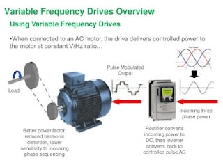
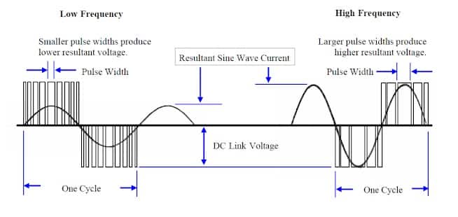
How PWM Maintains V/f Ratio
In a VVVF drive, a Pulse Width Modulated (PWM) inverter is used to adjust both parameters proportionally.
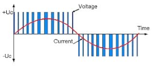
- As frequency increases, PWM pulse width increases → Higher output voltage
- As frequency decreases, pulse width reduces → Lower output voltage
Example:
For a 440V, 50Hz motor:
V/f=440/50=8.8
To operate at 25Hz:
V=25×8.8=220V
Maintaining this constant V/f ensures constant flux and torque.
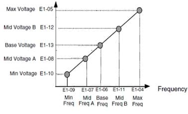
The PWM inverter’s output voltage increases linearly with an increase in frequency.
Relationship between Voltage and Frequency in VFD
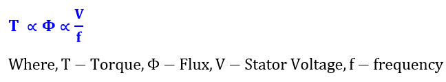
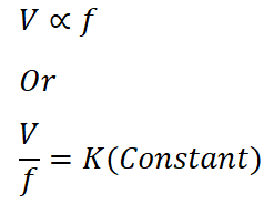
To maintain motor performance, voltage must be proportional to frequency:
Voltage ∝ Frequency
This ensures that the magnetic flux (ϕ) in the core remains constant.
How Constant V/f ratio Maintain Constant Flux in VFD?- Mathematical Proof
The flux produced in the motor core can be calculated with the formula given below.
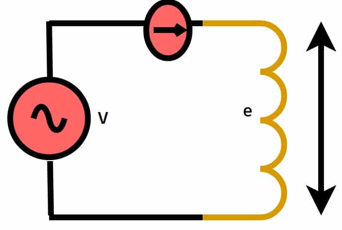
According to Faraday’s law of electromagnetic induction, the self EMF induced generated in the stator is expressed as;
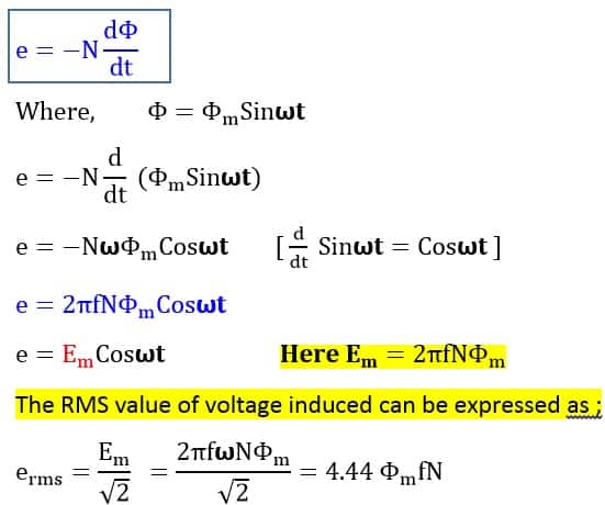
Where erms is the back EMF/phase produced in the stator, f-frequency, and n-number of turns in the stator coil.
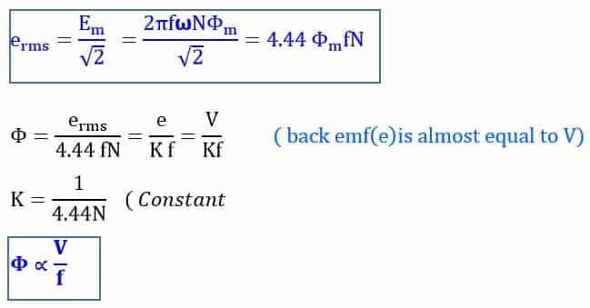
So, to keep ϕ (flux) constant, the ratio V/f must remain constant.
What Happens If V/f is Not Maintained?
Case 1: Over-Fluxing (Too High V/f)
If voltage is not decreased while reducing frequency, the V/f ratio increases → flux increases → core saturation → overheating → winding failure.
Example:
440V, 50Hz → V/f = 8.8
If frequency is reduced to 25Hz but voltage remains 440V → V/f = 17.6
Flux becomes 2× rated, leading to core damage.
Case 2: Under-Fluxing (Too Low V/f)
If frequency is increased but voltage is not increased proportionally → V/f reduces → flux weakens → torque drops.
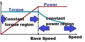
Flux Weakening Region – Above Base Speed
Above the rated frequency (e.g., >50Hz), the voltage cannot be increased further due to supply limits.
- Above base speed → Constant Power Region
- Below base speed → Constant Torque Region
In flux weakening mode:
- Torque decreases
- Speed increases (up to ~10–20% higher)
Note: Check motor design before applying flux weakening,
Conclusion
Maintaining a constant V/f ratio in VFD or VVVF drives is fundamental for:
- Preserving core magnetization without saturation
- Enabling consistent and efficient torque delivery across varying speeds
- Preventing overheating, insulation damage, and eventual motor failure
If the V/f ratio is not kept constant, it leads to under- or over-fluxing, severely impacting motor efficiency, reliability, and lifespan.
→ That’s why constant V/f control is a cornerstone of modern VFD motor drive systems.

Related Articles:
- Applications of Variable Frequency Drives(VFDs)
- Preventive Maintenance of Variable Frequency Drive(VFD)
- What is a VFD? – Its Working, Applications, Advantages
- DC Injection Braking in VFD- Variable Frequency Drive
- Understanding Braking Theory in VFD
- What is the Difference between Soft Starter and VFD?
- Controlling Multiple Motors with one VFD
- Why Insulated Bearing is used for VFD driven Motor?
Very informative and insightful article
Good lesson and explanation.
Thank you