This guide explains effective harmonics mitigation techniques—including equipment selection, tuned and de-tuned filters, and active filters—to reduce distortion, improve reliability, and ensure compliance with power quality standards.
What is Harmonics?
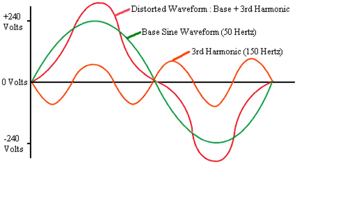
Harmonics are unwanted frequencies that distort electrical waveforms, reducing power quality and system efficiency.
Harmonic is a wave whose frequency is integral multiples of the fundamental frequency. The harmonics are a power quality problem that needs to be addressed during equipment selection.
The harmonic mitigation using filters can be adopted to mitigate the harmonics in the existing installation.
Read deatailed article on: Harmonics and Harmonic Frequency in AC Circuits
Harmonics Mitigation Techniques
The various harmonics mitigation techniques are equipment selection, tuned and de-tuned filters, active filters, and hybrid filter solutions.
Equipment Selection
Impact of Drives and Non-Linear Loads
Speed control of the induction motor can be achieved through variable frequency drives (VFDs) and a slip power recovery system. The speed control of the DC motor can be regulated by DC Drive.
All these drives are categorized into non-linear load categories.
The AC and DC drives draw non-linear currents when sinusoidal voltage is applied. Because of non-linearity in applied voltage and current, the drives generate harmonics in the system.
The magnitude of the harmonics current is different for the different orders of harmonics. The lower the harmonic order, the higher the magnitude of the current.
Harmonic Current Calculation
The magnitude of the harmonic current can be expressed with the following formula.
The Harmonic current of the nth-order harmonics
= Magnitude of Fundamental current/n
Where the n=order of harmonics
If the fundamental current of the drive at 50 Hz frequency is 100 Ampere, then the 5th-order harmonic current will be 20 Amp. (100/5) and the 7th order harmonic current will be 14.28 Amp(100/7). The harmonic current of the 25th-order harmonic is 4 Amp (100/25).
From above, it is clear that the combined harmonics current due to the 5th & 7th order harmonics is 34.28 amperes, which accounts for about 34 % of the total harmonics current.
The harmonics current is basically a reactive current drawn from the system. Because of increased reactive current due to harmonics, the apparent current (VA) demanded from the supply source increases.
In addition to increased apparent power, many more problems, such as power loss, temperature rise of electrical equipment, and nuisance tripping of electronic equipment, creep into the electrical network.
Passive Filter
Tuned Harmonic Filter
A tuned filter works on the principle of providing the least impedance path for one or two harmonic frequencies and has a tuning frequency that is within +/- 10 % of the harmonic frequency to be filtered.
Tuned filters of particular harmonics order carry more harmonic current as they offer low impedance to the dominant harmonics. Therefore, the tuned filter design has to be done carefully.
The tuned filter is formed with a combination of inductance and capacitance, so it is bulkier than the de-tuned filter and active filter.
The tuned filters can be installed only after a detailed harmonics study. Tuned filters do not adapt easily to changes in power network configuration, and their efficiency is usually altered when network configuration changes.
When new non-linear loads are added to the network after filter installation, a fresh harmonic study must be conducted.
Multiple tuned filters must be connected in parallel when filtering more than one harmonic frequency. The self-resonant frequency of a filter depends on the tuning factor, which is the percentage ratio of its inductive to capacitive reactance
A major drawback of tuned filters is the risk of resonance, which occurs when the network’s inductive reactance equals its capacitive reactance. This resonance can lead to the failure of power factor correction capacitors.
De-tuned Harmonic Filter
To solve this issue of resonance, the filter is deliberately detuned for the particular harmonic order.
For example, the filter for 5th-order harmonics current is designed for a frequency lower than 250 Hz. With detuning, some percentage of the harmonics current remains unfiltered, but the resonance can be avoided.
The tuning factor can be given to the tuned filters to avoid the resonance problem.
The tuning factor and tuning frequency of the harmonic filter are given by the following expressions:
Tuning factor, p (%)
=[(Inductive reactance) / ((Capacitive reactance)] x 100
= (XL/XC )*100
Filter Tuning frequency
Fr=Fs/√0.01p Hz (P is in percentage)
For 5 % detuning
Fr=50/√ 0.05 = 224 Hz
Where fs = Fundamental system frequency
Filter Frequency with De-tuning
| De-tuning Factor (%) | Filter Frequency (Hz) |
| 5 | 224 |
| 7 | 189 |
| 8 | 177 |
| 14 | 134 |
Active Harmonic Filter
The PWM INVERTER technology is the basic building block of an Active Harmonic Filter. Active filters are new-generation harmonic filters that use modern technologies and devices to provide revolutionary filtering solutions.
The active filter produces the harmonic current spectrum in phase in opposition to that produced by the non-linear loads, and these generated harmonic currents of the active filters are injected into the system in real-time to ensure the effective cancellation of all harmonics present in the network.
In addition to canceling the harmonic current, the active filter is also capable of improving the power factor by providing both capacitive and inductive reactive power in a step-less manner.
At present, active filters are the most technologically advanced solutions available for harmonic filtering.
The active filter uses a CPU to detect the order and magnitude of the harmonics present in the network. It generates a harmonic current spectrum in phase opposition to the measured spectrum.
Read detailed article on: Working Principle of Active Harmonic Filter
Order of Harmonics
Role of Pulse Configuration
If the drives are selected for higher power rating motors, they must have 12-pulse system configurations.
For example, if the motor rating is 350 KW, 625 Amp, 440 Volt, and if it is run on the inverter with a 6-pulse system configuration, then the 5th & 7th order harmonics current will be 125 amperes & 90 amperes respectively.
If the motor is run on the inverter of the 12-pulse system configuration, the 5th & 7th-order harmonics current will be completely eliminated.
Harmonics Order Formula
Let us first understand the number of pulse system configurations in the terminology of inverter and converter. The number of pulses depends on the configuration of the converter or inverter.
In a three-phase system, when the three-phase supply is fed to the converter, the number of pulses is 6. The number of pulses is equal to twice the number of phases.
The order of harmonics generated in the system can be expressed with the following formula.
N= PK +/- 1
Where P= No. of pulses
K= Integral Multiples, K = 1, 2, 3, 4……
For the Six Pulse system,
N= 6*1 +/-1 = 6-1, 6+1
= 5, 7
Harmonic Order Table
| No. of phases(m) | No. of pulses(p)= 2*m | Harmonics Order(n)= PK+/-1 |
| 3 | 6 | 5,7,11,13,17,19,23,25,29,31,35,37… |
| 6 | 12 | 11, 13, 21, 23, 35, 37……………….. |
| 18 | 36 | 35, 37……………………… |
The order of harmonics generated in the system depends on the pulse configuration of converters and inverters. Therefore, it is important to select the equipment that generates the least harmonic distortion.
Harmonic Filter Selection
Though all orders of harmonics are harmful to an electrical power system, the 5th and 7th-order harmonics are most harmful to the electrical network. One solution to mitigate these lower-order harmonics is to install harmonic filters.
Harmonic filters can be categorized into three categories: passive filters, active filters, and hybrid filters.
The passive filter has passive components like a resistor, inductor, and capacitor. The active filter is designed using active components like semiconductor devices like IGBTs.
Hybrid filters are basically a combination of active and passive filters. To make the installation cost-effective, hybrid filters mitigate the lower-order harmonics using the passive filters and the higher-order harmonics using the active filters. A combination of the active and passive filters is known as a hybrid filter.
The passive filters can be further categorized into tuned and de-tuned filters. The frequency of the 5th and 7th order harmonics is 250 & 350 Hz, respectively.
The passive filters are generally used for mitigation of 5th and 7th-order harmonics because the magnitude of the current of lower-order harmonics is more than the magnitude of the current of higher-order harmonics.
Read detailed article on: Harmonic Filter Selection
Related Articles:
Very good and interesting article sir. This not only revises the topics I studied in Bachelor's Engineering, but, gives more understanding with your words. Thank you so much.