We will discuss the types of chopper circuits in this article. There are different types of choppers circuits. The chopper circuits are classified according to their operation in different quadrant.
Innovation of high-power semiconductor switches has started a new era in the power sector. It has introduced a new area of power control in electrical engineering. Power control has enhanced the research activities in every sector of science as it can control power from low to high voltage levels in both AC(using inverters) and DC(using rectifier and chopper) forms.
Our distribution system is of 240V ac, to convert this AC into DC, we use a rectifier circuit. A lot of house appliances are based upon low dc voltage which is controlled by a chopper. It has enhanced the sectors of medical instrumentation, microelectronics, and machine control. It is majorly used in dc and ac machine speed control and dc voltage regulator.
What is a Chopper Circuit?
The chopper circuit converts fixed DC to variable DC. A chopper is a DC to DC converter circuit which controls voltage levels from input to output. Therefore, it is also called a transformer for a dc circuit system.
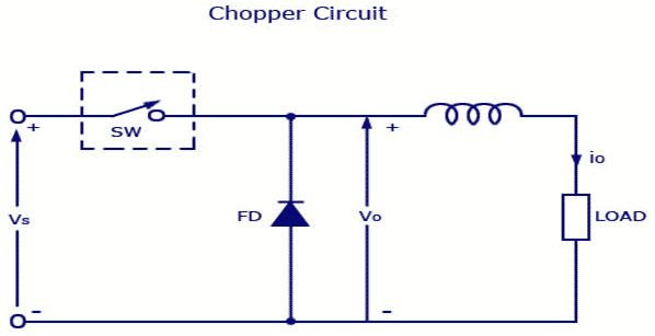
Principle of Operation
This type of circuit uses an inductor as an energy-storing element that collects energy from the input source and releases it to the output load circuit. In a chopper circuit, the semiconductor switch controls the power from the source to the load. The value of the inductor, load (resistor), and switching frequency decide the continuity of the circuit. The chopper circuit has an ON/OFF switch that can rapidly connect or disconnect the source to load connection. The chopper circuit receives continuous dc voltage, Vs, and outputs voltage V0.
Types of Chopper Circuits
Unidirectional semiconductor switches are used in chopper circuits. Arranging the switches in a different manner, it is possible to form different quadrant choppers. There are five types of choppers. Types of choppers are type A, type B, type C, type D, and type E.
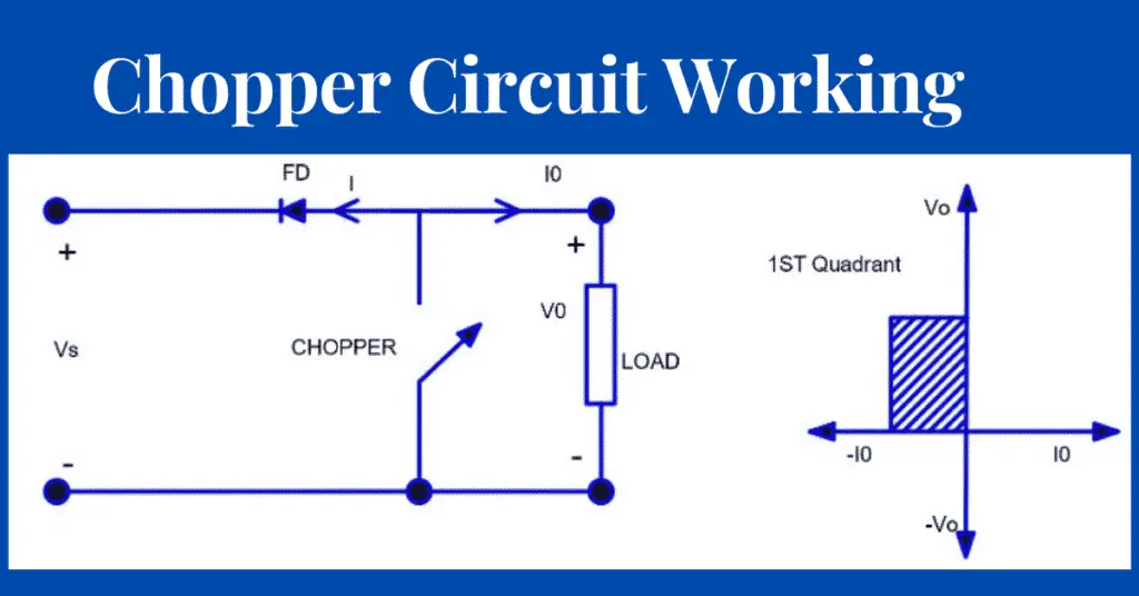
Type-A Chopper
This type of chopper is also known as 1st quadrant chopper. This type of chopper is applicable to the inductive load or motor load. When the chopper is on, the source connects to the load, and when the chopper is off, the stored energy in the inductive load circulates through the freewheeling diode.
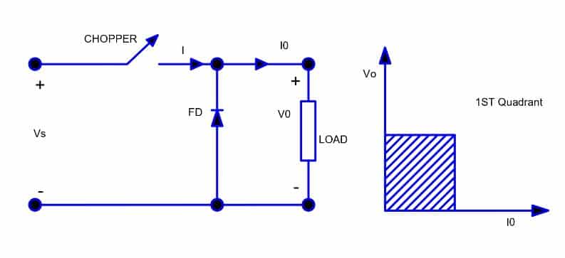
In this case, chopper V0 & I0 will always be positive, as shown in the first quadrant. In a type-A chopper, power flow is always from source to load. This chopper is also called a step-down chopper. The average value of output voltage is less than or equal to the input voltage.
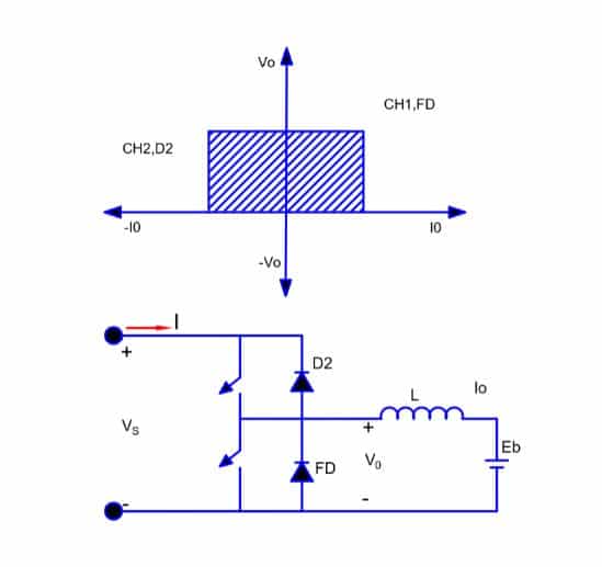
Type-B Chopper
This is also known as the second quadrant chopper. V0 will be positive always but Io will be negative. In this case, power flow is from load to source. Like in DC motor during regenerative braking power flows from Eb (back EMF) to the source i.e Power flow is negative.
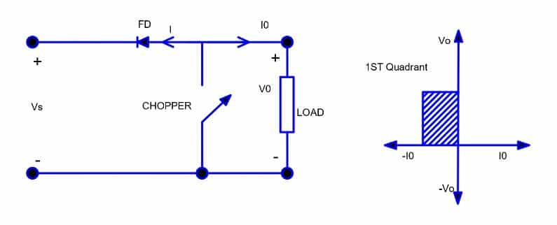
In this case, when the chopper is on, V0 is zero but back EMF drives current through the inductor. During turn-off, V0=L di/dt + Eb which is more than the source voltage sends power into the source. For the dc motor case, during regenerative braking speed is more than the rated speed, which implies the stored kinetic energy is more than the rated power and that excess power takes place to the source through a freewheeling diode.
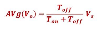
The average output of the chopper circuit is;
Type-C Chopper
Type-C chopper is made by connecting Type-A and Type-B in parallel. We will always get o/p voltage positive. “When the chopper is on the freewheeling diode starts conducting and the output voltage v0 will be equal to Vs. The direction of the load current i0 reverses.
The current i0 will be flowing towards the source and it will be positive regardless the chopper is on or the FD conducting. The load current will be negative if the chopper or the diode D2 conducts. We can say the chopper and FD operate together as a type-A chopper in the first quadrant. In the second quadrant, the chopper and D2 will operate together as type –B chopper.”
The average output voltage will be always positive but the average load current might be positive or negative. The power flow may be like the first quadrant operation i.e from source to load or from load to source as the second quadrant operation. The circuit can perform like one type of chopper switching on both the chopper will short circuit the source.
Type D Chopper
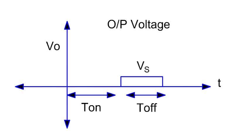
The circuit diagram of the type D chopper is shown in the below figure. When the two choppers are on, the output voltage v0 will equal Vs .” When v0 = – Vs the two choppers will be off but both the diodes D1 and D2 will start conducting. “V0 the average output voltage will be positive when the choppers turn-on the time Ton will be more than the turn off time Toff its shown in the waveform below. As the diodes and choppers conduct current only in one direction, the direction of load current will be always positive.
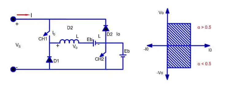
The power flows from source to load as the average values of both V0 and I0 are positive. From the waveform, it is clear that the average value of V0 is positive. Thus, we get the fourth quadrant operation of the type D chopper.
Type E Chopper
It is also called a four-quadrant chopper.
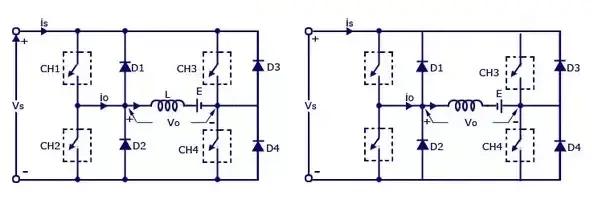
Type E or the fourth quadrant chopper consists of four semiconductor switches and four diodes arranged in antiparallel. The 4 choppers are numbered according to which quadrant they belong. Their operation will be in each quadrant and the corresponding chopper only be active in its quadrant.
Applications of Chopper Circuits
Chopper circuits are used for the following applications.
- SMPS- Switched-mode power supplies
- DC to DC converters
- Speed controllers of DC motor
- Class D electronics amplifier
- For switching capacitors
- Variable frequency drives
- For boosting D.C. voltage
- Battery-operated electric cars
- Battery chargers
- Railway traction
- Lighting and lamp controls
Read Next: