The Zener diode, as a voltage regulator, is used to get the fixed DC voltage for electronic circuits. In this post, we shall learn designing of a zener voltage regulator. The construction of the zener diode is similar to the p-n junction diode. The zener diode is heavily doped as compared to the ordinary diode. The p-n junction diode gets damaged if the reverse voltage exceeds its specified reverse breakdown voltage.
The zener diode functions similarly to the p-n junction diode in forward-biased conditions. The zener diode is designed to work for a specified breakdown voltage in the reverse bias. The zener diode works well in the specified reverse breakdown region. Contrary to the ordinary diodes, the depletion region is again regained by the zener diode when the reverse voltage is removed. This salient feature of the zener diode makes it suitable for the voltage regulators.
The zener diode is widely used as a voltage regulator. To understand the working of the zener diode, let us understand the voltage/current curve of the zener diode. The VI characteristics of the Zener diode are given below.
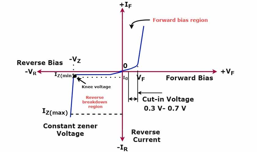
When the Zener diode is forward-biased, the diode starts conducting when the voltage exceeds the cut-in voltage of the diode. The characteristics of the zener diode in forward biasing are similar to the standard p-n junction diode.
When the reverse voltage is applied, the zener diode has high resistance, and negligible current passes through the diode if the applied reverse voltage is less than the breakdown voltage of the zener diode. If the reverse voltage is increased and when the voltage is equal to the reverse breakdown voltage of the diode, the zener diode starts conducting.
The phenomenon of the current flowing through the Zener diode when the applied voltage is equal to or more than the specified breakdown voltage of the Zener diode is called the Zener breakdown.
If the voltage is further increased above the specified zener breakdown voltage, the current through the diode increases, but the voltage across the diode remains almost constant. The zener diode is available in the range of 1 to 200 volts.
| Zener Diode | Zener Voltage(Vz) |
| 1N4747A | 20V |
| 1N4748A | 22V |
| 1N4749A | 24V |
| 1N4750A | 27V |
| 1N4751A | 30V |
| 1N4752A | 33V |
| 1N4753A | 36V |
| 1N4754A | 39V |
| 1N4755A | 43V |
| 1N4756A | 47V |
| 1N4757A | 51V |
| 1N4758A | 56V |
| 1N4759A | 62V |
| 1N4760A | 68V |
| 1N4761A | 75V |
| 1N4762A | 82V |
| 1N4763A | 91V |
| 1N4764A | 100V |
Designing of Zener Voltage Regulator
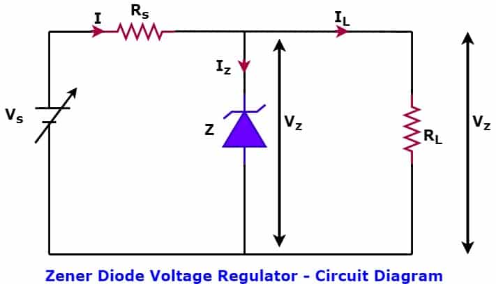
The circuit diagram of the voltage regulator is shown below.
The following conditions must be met to function the zener diode as a voltage regulator.
1. The Zener diode must be connected in the reverse bias.
2. The supply voltage Vs must be more than the Zener breakdown voltage
In the circuit above, the Zener diode D is connected in reverse bias. The resistance Rs is connected in the series connection of the diode to limit the current flowing through it. The zener diode maintains the constant output voltage Vo regardless of the input voltage variation or load current variation. Let us understand how the Zener diode in the above circuit maintains the constant output voltage with variations in the supply voltage and load current.
Case1- When the output is not connected to the load
When the output is not connected to the load, the supply current I equals the Zener current. The resistance is connected to the series of diodes that limit the zener current in the safe operation region. The correct selection of the series resistance is necessary for operating the Zener diode as a voltage regulator.
If the resistance value is selected too high, the current through the Zener diode will be too low to pass the current through the Zener diode, and, in this condition, the output voltage V0 will be equal to the supply voltage Vs. The output voltage will be equal to the Zener Voltage only if the Zener starts conducting. The Zener current(Iz) should not exceed the maximum current rating of the diode.
Rs(Min) = (Vs-Vz)/ Iz(max)
Case2- When the input supply varies in the specified range
When the input voltage is at its maximum in the specified voltage range, the increased voltage increases the Zener Current(Iz). In the reverse VI characteristics of the Zener diode, if the reverse voltage increases above the Zener breakdown voltage, the current through the Zener diode increases, and the voltage across the diode remains constant.
I = Iz + IL
The increased supply voltage causes an increase in the Zener current. Thus, the input supply current( I ) increases proportionately to the increased Zener current, and the load current and voltage across the load ( IL x Rs = Vz) remain pretty constant.
When the input supply voltage is at a minimum in the specified voltage range, the Zener current decreases, and consequently, the input supply current I decrease. The decreased Zener current should not be less than the specified minimum Zener Current(Iz-Min); otherwise, zener conduction will stop. The output voltage and load current remain constant if the current flowing through the diode equals or exceeds the rated minimum Zener current(Iz-min).
Case3- When the load current increases
With an increase in the load current(IL), the Zener current(Iz) decreases, and thus, the total current(I) remains constant. The Zener current may reach the minimum Zener current(Iz-min). If the Zener current decreases below the rated minimum Zener current(Iz-min), the Zener diode behaves as an open circuit.
With a decrease in the load current(IL), the Zener current(Iz) increases, and thus, the total current(I) remains constant. The Zener current may reach the maximum Zener current(Iz-max). If the Zener current increases above the rated maximum Zener current(Iz-max), the Zener diode may get permanently damaged.
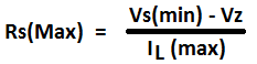
Selection of Circuit Components:
The value of series resistance can be expressed with the following mathematical formula.
Selection of Zener Diode:
The following data of the Zener diode should be known.
- Zener minimum current
- Zener maximum current
- breakdown voltage or Zener Voltage
- Power rating of the Zener diode