💡Key Takeaways

Diode Current Equation Explained: The diode equation is a mathematical formula that illustrates the relationship between the current flowing through a diode and voltage applied across it.

Critical Components: It involves key parameters such as the dark saturation current and the ideality factor, which are essential to grasping the diode's behavior.

Forward vs. Reverse Bias Operation: When the diode is forward-biased, it permits a significant current flow. Conversely, the current is minimal in reverse bias due to a negligible exponential term.

Influence of Temperature: The diode's performance is affected by the thermal voltage, approximately 25.87 mV at room temperature.

Diode Current Equation Derivation: Knowing how to derive and use the diode current equation is crucial for effectively applying diodes in electronic circuits.

Solved Numerical Problem: It will help you understand the diode current equation and its applications.
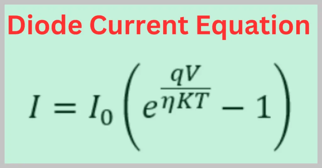
The diode current equation shows the relationship between the current flowing through the diode as a function of applied voltage. The mathematical formula of the diode current is given below.
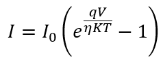
Where,
I = current flowing through the diode
Io = reverse saturation current
q = the charge of the electron
V = the voltage applied across the diode
η = the exponential ideality factor of the diode
K = the Boltzmann constant and K = 1.38 x 10⁻²³ J/K
T is the absolute temperature in Kelvin
The diode current equation is also known as the Shockley diode equation or the diode law, named after transistor co-inventor William Shockley of Bell Labs.
The current flowing through the diode does not vary linearly with an increase in applied voltage. The V-I characteristics of the diode have an exponential relationship. The diode resistance varies with an increase in the temperature. As a result, the current does not vary linearly with voltage. The diode is a non-ohmic and nonlinear semiconductor device.
Key Parameters of Diode Current Equation
Let us understand what factors the diode current depends on.
Reverse Saturation Current(I0):
The current flowing through the p-n junction diode when it is reversed-biased is called reverse saturation current. The minority carriers are responsible for this current. In a PN junction diode, the reverse saturation current is due to the diffusive flow of minority electrons from the p-side to the n-side and the minority holes from the n-side to the p-side.
The reverse saturation current of the diode is in the range of μA to nA. The reverse saturation current gets doubled for every 10-degree centigrade rise in temperature.
The cut-in voltage ( the voltage at which the diode starts conducting) is not directly dependent on the reverse saturation current. Instead, it is more related to the diode material and the temperature. However, the reverse saturation current does affect the diode’s forward current characteristics.
The reverse saturation current I0 increases with temperature. Since the cut-in voltage is slightly temperature-dependent, it can indirectly be influenced by changes in I0. A higher I0 implies the diode will have a slightly higher forward current for a given forward voltage.
η, the (exponential) Ideality Factor
Ideality factor is a way of measuring how accurately the diode follows the ideal diode equation. If the diode under consideration behaves precisely like an ideal diode, then η will be 1. Its value increases from 1 as the difference between the behaviors of the ideal diode and the diode under consideration increases.
The greater the deviation, the greater the value of η. The value of η is 1 for germanium diodes and 2 for silicon diodes. The ideality factor depends on the following parameters of the diode.
- Electron Drift
- Diffusion
- Carrier Combination in the depletion region
- Doping Level
- Manufacturing Process
- Purity of the material
The value of ideality factor η generally lies between 1 and 2.
Read detailed article on:
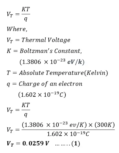
Thermal Voltage (VT)
Thermal voltage is the voltage equivalent of the thermal energy of charge carriers in a diode. It is given by:
VT=kT/q
Where:
- k=1.38×10⁻²³ J/K is the Boltzmann constant
- T = absolute temperature in Kelvin
- q=1.6×10⁻¹⁹ C is the charge of an electron
At room temperature (300 K), VT≈25.9 mV
Though small, this value strongly influences the exponential current–voltage relationship of the diode and increases linearly with temperature.
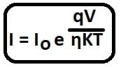
Diode Current Equation in Forward Biased Condition
When the diode is in a forward-biased condition, a large forward current flows through it, and the value of the exponent term is more significant.
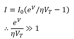
The diode current equation in forward bias becomes
Diode Equation in Reverse Biased Condition
When the diode is reverse-biased, the exponential term becomes negligible, and the diode current is equal to the reverse saturation current.
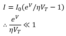
I = – Io
Diode Equation at Room Temperature
Let the room temperature be 27°C.
Temperature in Kelvin T = 273 + 27 = 300 K.
K =1.38 x 10⁻²³ JK-1
q =1.6 x 10⁻¹⁹ C
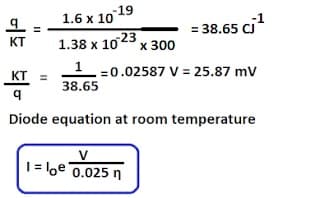
The ratio KT/q is called the thermal voltage of the diode.
At standard room temperature, the behavior of the diode is affected by the thermal voltage, which is approximately 25.87 mV.
Solved Problems on the Diode Current Equation
A silicon diode at room temperature (27°C) with a saturation current (I0) of 10-12A is subjected to a forward voltage (V) of 0.7V. Calculate the forward current (I) assuming an ideality factor (n) of 1.
Given Data:
- Reverse saturation current, I0=10−12 A
- The voltage across the diode, VD=0.7 V
- Ideality factor, n=1
- Temperature, T=273+27=3000 K
First, calculate the thermal voltage VT.
Now, substitute the values into the Shockley diode equation
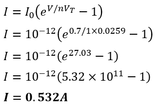
Therefore, the diode current I is 0.532 A.
Diode Current Equation Derivation
The expression for the total current of a diode as a function of the applied voltage (the volt-ampere characteristics) can be derived by assuming that the depletion width is zero.
When a diode is forward biased, holes are injected from the p-side into the n-side, increasing the concentration of holes, denoted as p, in the n-side above its thermal equilibrium value, Pno.
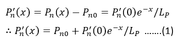
Where Lp represents the diffusion length for holes in an n-type semiconductor.
The injected or concentration at x=0 is
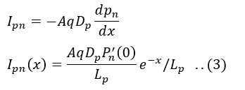
The diffusion hole current in n- side is given by
Since,
Therefore,
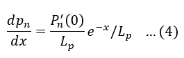
From the given equation, it is clear that the hole current decreases exponentially as distance increases.
Similarly,
Since the injected concentration depends on the voltage applied across the p-n diode, we can conclude that Ipn is dependent on the applied voltage V. Now, let’s explore the relationship between P’n(0) and V.
From the Boltzmann relationship of kinetic theory:
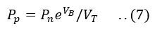
Where.
-Pp and Pn are hole concentrations at the edge of the space charge region in p and n material, respectively.
-VB is the barrier potential across the depletion layer
-VT is Thermal voltage
Consider a pn-junction biased in a forward direction by an applied voltage V. Then the barrier voltage VB is decreased from its equilibrium value V0 by the amount V, or VB= V0-V.
The hole concentration remains constant throughout the p-region at the thermal equilibrium value Pp= Pp0, while it varies with distance into the n-side, as shown in the figure below.
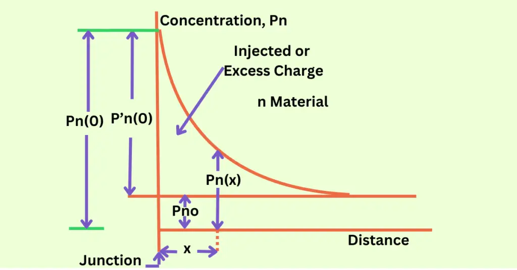
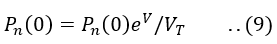
At the edge of the depletion layer, i.e. at x=0 Pn=Pn(0)
Therefore, the Boltzmann relationship, in this case, is
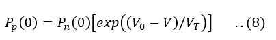
Since,
In an unbiased pn-junction diode, under equilibrium conditions,
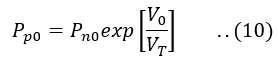
Therefore by combining the above equation equation and equation(8), we obtain
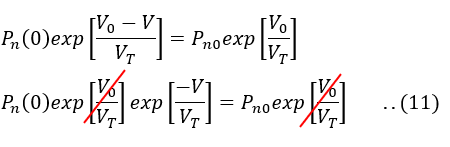
Therefore,
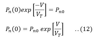
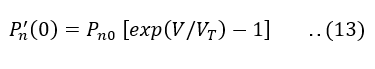
This boundary condition of the above equation is called the law of junction.
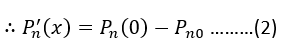
Thus, the hole concentration P’n(0) injected into the n-side at the junction is,
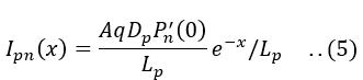
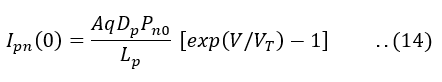
Thus, the hole current crossing the junction into n-side, with x=0, is,
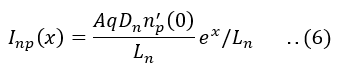
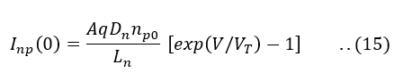
Similarly, the electron current crossing the junction into the p-side, with x=0, is given by,
Finally, the total current I is the sum of Ipn(0) and Inp(0)
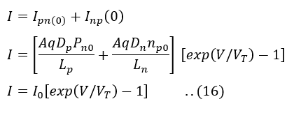
Where,
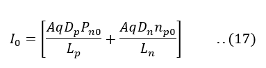
I0 is the reverse saturation current
Throughout this discussion, we have not considered the generation and recombination of carriers in the space-charge region. This assumption holds true for a germanium diode but not for a silicon device. If we do take into account carrier generation and recombination in the space-charge region, the general equation for diode current is as follows:
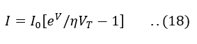
Where, For silicon η=2 and germanium η=1
Related Articles:
- Ideality Factor of Diode
- Diode Resistance – Static, Dynamic, and Reverse Resistance
- PN Junction Diode and its Characteristics
- Photodiode
- What is Knee Voltage of PN- Junction Diode?
- What is Thermal Voltage? Definition, Formula & Value at 300K
1 thought on “Diode Current Equation & Its Derivation”