In this article, we shall discuss how to test the SCR using a multimeter. For troubleshooting of the electronic card especially the power circuit diagram, knowledge of SCR testing with the simplest method is a must. The first thing we should know about the leads of SCR- anode, cathode, and gate. The SCRs are available in different packages To-92, stud base, discrete plastic, and press pack, and each package has a different pin configuration. For SCR leads configuration identification, the components data sheet is the best source.
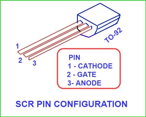
How to Identify the terminals of the SCR
Now, for understanding, we take the SCR TO-92 package for reference.
Identify the terminals of the Multimeter
- Using a P-N junction diode, we can find out the polarity of the multimeter leads. Junction diode is unidirectional and diode has low resistance in forward biasing and high resistance in reverse biasing.
- Now, connect the multimeter leads to the anode and cathode of the diode. If the multimeter reads low resistance then the multimeter lead connected to the anode of the diode is positive lead and the other lead is negative.
- If ohmmeter reads high resistance then it shows the reverse bias state of the diode. In this condition, the lead connected to the anode is the negative lead of the multimeter and the lead connected to the anode is the positive lead of the multimeter.
- Generally, the positive lead of the multimeter has its connection in the red socket of the multimeter.
Procedure to Test the SCR with the help of Multimeter
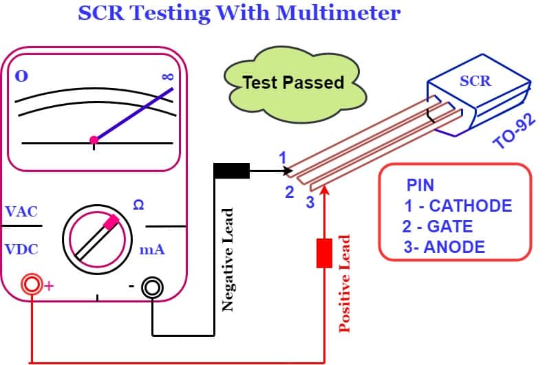
- Keep the multimeter in ohm mode.
- Connect the positive lead of multimeter to an anode of SCR and negative lead of multimeter of cathode lead.
- As per step No. 2, SCR is in forward blocking mode. The SCR does not conduct. In this condition, the SCR must show infinite resistance and there will be no continuity buzzer. If the resistance of the SCR is high then the SCR is OK as per this test.
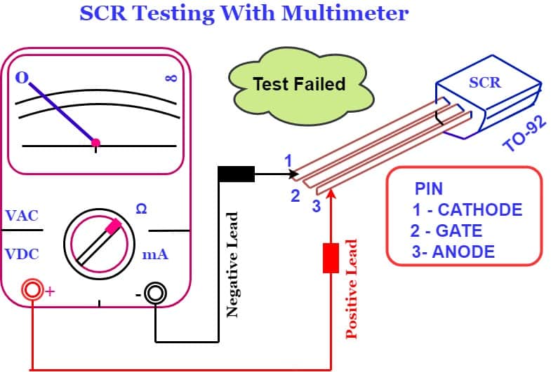
- The SCR if shows continuity in step No.3, the SCR is short circuit and SCR is defective.
- If SCR passes in step No.3, Further we test it for its gate circuit functionality.
- Connect the positive lead of the multimeter to the anode terminal and the negative lead of the multimeter to the cathode of SCR.
- Now, connect the gate through a wire to the anode. If you recall this is the forward conduction mode of the SCR. The SCR must be turn on. The resistance measured across anode and cathode should be zero. If resistance is zero, it means SCR is in conducting mode. We can say SCR is OK.
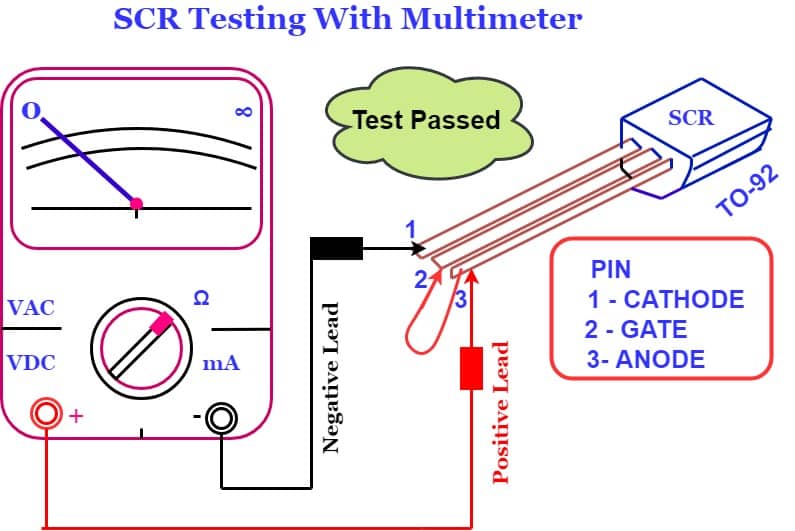
- When the gate lead is removed from the anode, conduction may stop or continue depending on whether the ohmmeter is supplying enough gate current to keep the device above its holding current level. If SCR keeps conducting then it is the latching condition of SCR.
Limitation of SCR Testing with Multimeter
The testing of the SCR & its results depends on the supply current of the multimeter. If the multimeter supplies sufficient current for SCR conduction, then we can test the SCR with a multimeter.
Another method of SCR Testing
SCR tester circuit diagram
The circuit diagram of another test method is given below.
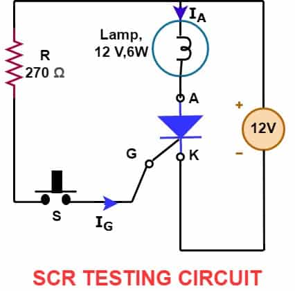
Almost all types of SCR can be checked using above SCR tester circuit diagram.
Test Procedure
- Connect the SCR in the test circuit zig.
- Apply 12 Volt across anode and cathode of SCR. Connect anode to positive supply and cathode to the negative supply. The lamp should be off in this condition. It shows that SCR is in OFF condition.
- Press switch “S” momentarily so that gate of SCR gets a gate current pulse. The SCR must turn on and must remain in ON state. The SCR should be in a latched condition. In this condition, the lamp must turn on and should remain in its on state till the 12 volt supply is switched off.
- If the above checks are positive then the SCR is OK.
Related Posts :