A current transformer (CT) is an instrument transformer that reduces high alternating current (AC) to a safe, standardized current. The secondary output is typically 5 A or 1 A. This allows measuring instruments and protective relays to monitor high-current circuits safely.
Current transformers are used in almost every electrical power system. You can find them in power plants, substations, industrial switchgear, motor control centers (MCCs), commercial buildings, and renewable energy plants. They provide accurate current measurements and help protect electrical equipment from faults.
Modern current transformers are available in different types, ratios, accuracy classes, and ratings. Therefore, choosing the right CT requires an understanding of several important parameters, such as the CT ratio, burden, accuracy class, and application.
This guide covers everything you need to know about current transformers. You’ll learn their construction, working principle, types, specifications, ratings, applications, advantages, and selection criteria.
What is a Current Transformer?
A current transformer (CT) is a type of instrument transformer that converts a high alternating current into a proportional low current. The reduced current can then be measured safely using standard electrical instruments.
Unlike a power transformer, a current transformer is not designed to transfer electrical power. Instead, its primary purpose is to measure current and supply accurate current signals to protective relays.
The secondary current is usually standardized to 5 A or 1 A. As a result, the same measuring instrument can be used for electrical systems with different current ratings by selecting a suitable CT ratio.
Example:
Suppose a 200/5 A current transformer is installed on a feeder.
- Primary current = 200 A
- Secondary current = 5 A
If the primary current decreases to 100 A, the secondary current also decreases proportionally to 2.5 A. This fixed relationship enables accurate current measurement across a wide operating range.
Why is a Current Transformer Used?
Modern electrical power systems carry currents ranging from a few amperes to several thousand amperes. Measuring such high currents directly is neither practical nor safe, as it would require bulky instruments with heavy insulation and high current-handling capacity.
A Current Transformer (CT) solves this problem by stepping down high primary current to a standardized low value, typically 1 A or 5 A, making it suitable for standard measuring instruments and protective relays. At the same time, it provides electrical isolation between the high-voltage power circuit and the low-voltage measuring circuit, ensuring operator safety.
In addition to measurement, CTs play a critical role in power system protection. Protective relays continuously monitor the CT secondary current and detect abnormal conditions such as overloads, short circuits, and earth faults. When a fault occurs, the relay initiates a trip signal to the circuit breaker, isolating the faulty section and protecting equipment.
In summary, Current Transformers are used for safe current measurement, electrical isolation, and reliable protection in high-current electrical systems.
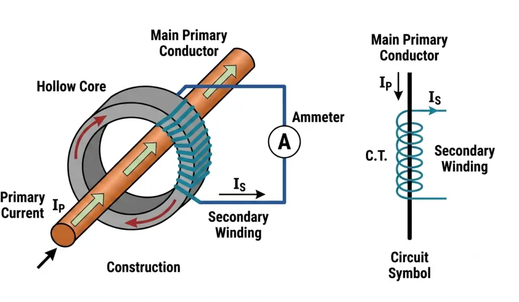
Construction of Current Transformer (CT)
A Current Transformer (CT) is constructed using a magnetic core, primary winding, secondary winding, and insulation system, which together form the basic construction of current transformer.
The core is made of high-permeability material to ensure efficient magnetic flux. The primary is either a single bar conductor or a few turns connected in series with the power line, while the secondary consists of finely insulated copper wire designed to deliver standard 1 A or 5 A output. The entire assembly is enclosed in a strong insulated housing for safe operation in high-voltage systems.
Working Principle of Current Transformer
The working of a Current Transformer is based on the principle of electromagnetic induction, similar to a power transformer but with a key difference: the CT operates with the secondary almost in short-circuit condition.
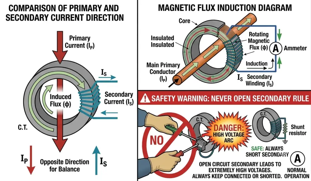
When alternating current flows through the primary conductor, it produces an alternating magnetic field in the core. This changing magnetic flux induces a proportional current in the secondary winding according to Faraday’s Law of Electromagnetic Induction.
The secondary current is directly proportional to the primary current, but scaled down by the turns ratio of the transformer. This allows safe measurement of very high currents using standard measuring instruments.
Mathematically, the relationship can be expressed as:
- Primary ampere-turns = Secondary ampere-turns
Since the secondary winding has many more turns than the primary, the current is reduced to a safe level.
CT Ratio (Current Transformer Ratio)
The CT ratio of a Current Transformer defines the relationship between the primary current and the secondary current. It indicates how much high primary current is stepped down to a lower, standardized value for safe measurement and protection purposes.
For example, a 200/5 CT ratio means that when 200 A flows in the primary conductor, the secondary winding produces 5 A. This allows measuring instruments and protective relays to safely monitor high currents without direct exposure to the power system.
Mathematically, CT ratio is expressed as:
Thus, a 1000/5 CT has a ratio of 200:1.
Proper selection of CT ratio is very important in power systems. An incorrect ratio may lead to measurement errors or improper relay operation during fault conditions. Standard secondary ratings are typically 1 A or 5 A, while primary ratings depend on system load requirements and application type.
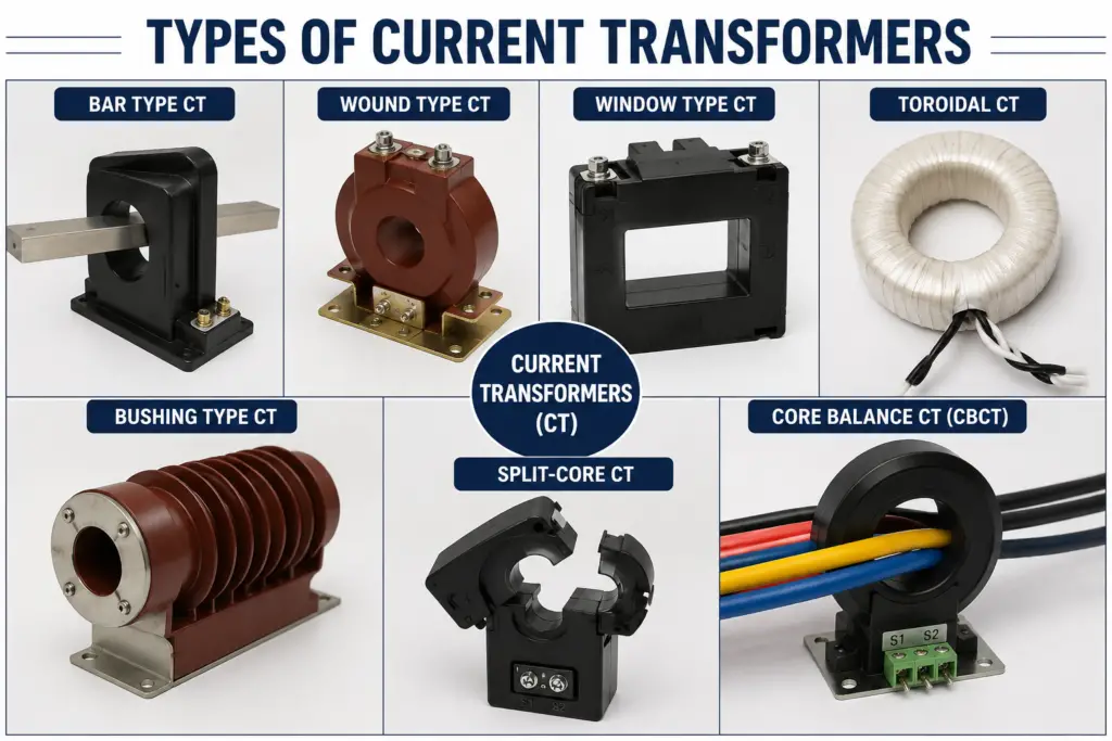
Types of Current Transformers
Current Transformers (CTs) are classified based on construction, application, and installation method. These types of current transformers are designed to meet specific requirements in measurement and protection systems, ensuring accurate current measurement, safe operation, and reliable performance in electrical networks.
1. Bar Type Current Transformer (CT)
In a bar type CT, the primary conductor is a fixed bar that passes through the core. It has a simple and rugged construction, making it suitable for high-current applications. Bar type CTs are commonly used in switchgear panels and power distribution systems.
2. Wound Type Current Transformer (CT)
In a wound type CT, both primary and secondary windings are physically wound on the magnetic core. This type is generally used for low current ratings where higher accuracy is required for measurement purposes. It is commonly used in testing and metering applications.
3. Bushing Type Current Transformer (CT)
A bushing CT is installed around the insulated bushings of power transformers or circuit breakers. It is compact in design and widely used in high-voltage substations for both protection and metering purposes.
4. Toroidal (Ring Type) Current Transformer (CT)
A toroidal CT has a circular ring-shaped core with no separate primary winding. The current-carrying conductor passes through the center of the core. It is widely used in energy meters and leakage current detection systems.
These different designs of Current Transformer ensure accurate current measurement and reliable protection across various power system applications.
Metering vs Protection Current Transformer (CT)
Current Transformers (CTs) are broadly divided into metering CTs and protection CTs based on their function in the power system. Both types are designed to step down high current to a standard value, but their performance characteristics and purpose are different.
Metering Current Transformer (CT)
A metering CT is designed for accurate measurement of current under normal operating conditions. Its main focus is high accuracy at or near rated load current. These CTs are used with energy meters, ammeters, and other measuring instruments. Metering CTs are carefully designed to have a low error ratio and stable performance within a limited current range. However, they may saturate quickly during fault conditions to protect the connected instruments.
Protection Current Transformer (CT)
A protection CT is used in protective relay systems to detect fault conditions such as short circuits and overloads. Unlike metering CTs, protection CTs are designed to perform accurately during high fault currents. They can withstand high current levels without excessive saturation, ensuring reliable operation of relays and circuit breakers.
In summary, metering CTs prioritize accuracy at normal load conditions, while protection CTs prioritize performance during fault conditions in electrical systems.
PS Class Current Transformer (CT)
A PS Class (Protection Special Class) Current Transformer is a special type of protection CT designed for high-accuracy protection applications, especially in differential protection schemes such as transformers, generators, and busbars.
Unlike standard protection CTs, a PS class CT is specified using excitation characteristics (CT magnetization curve) rather than a fixed accuracy class. This means its performance is defined by parameters such as knee point voltage, excitation current, and secondary winding resistance, ensuring very precise behavior under fault conditions.
The main purpose of a PS class CT is to maintain accurate current transformation during internal fault conditions, while remaining stable during external faults. This prevents unwanted tripping of relays and ensures reliable system protection.
A key parameter of PS class CTs is the knee point voltage, which is the voltage at which the CT core begins to saturate. Above this point, the CT should still maintain predictable behavior for correct relay operation.
PS class CTs are widely used in high-end protection systems where accuracy and stability are critical. They are typically found in differential protection of power transformers, generators, and large electrical equipment.
Accuracy Class of Current Transformer (CT)
The accuracy class of a Current Transformer (CT) defines how accurately the CT reproduces the primary current in its secondary circuit under specified operating conditions. It is an important parameter used to ensure reliable measurement and protection in electrical power systems.
Accuracy class is usually expressed in standard values such as 0.1, 0.2, 0.2S, 0.5, 1, 3, or 5 for metering CTs. A lower number indicates higher accuracy. For example, a 0.2 class CT or 0.2S class CT is more accurate than a 1.0 class CT, and is used in precise energy metering applications.
For protection CTs, accuracy classes are represented differently, such as 5P10, 10P10, or 5P20. In this notation, the “P” stands for protection, and the number before it indicates the allowable composite error percentage at rated accuracy limit factor. The number after “P” defines the accuracy limit factor, which shows how many times the rated current the CT can measure accurately during fault conditions.
Selection of the correct accuracy class is very important. Metering CTs require high precision at normal load, while protection CTs must maintain performance during high fault currents.
Proper accuracy class selection ensures correct billing in metering systems and reliable operation of protective relays in power networks.
Accuracy Limit Factor (ALF) of Current Transformer (CT)
The Accuracy Limit Factor (ALF) of a Current Transformer (CT) defines how many times the rated primary current a protection CT can carry while still maintaining its specified accuracy. It is an important parameter used mainly in protection CTs to ensure reliable performance during fault conditions.
For example, if a CT has an ALF of 10, it means the CT can accurately reproduce secondary current up to 10 times its rated primary current without exceeding the permissible error limit. So, a 100/5 CT with ALF 10 can maintain accuracy up to 1000 A primary current during fault conditions.
ALF is closely related to system protection because faults in electrical networks often produce very high currents. A CT with a proper ALF ensures that protective relays receive accurate current information even during these extreme conditions, allowing correct tripping of circuit breakers.
However, if the ALF is too low, the CT may saturate during faults, leading to inaccurate secondary current and possible failure of protection systems. On the other hand, a very high ALF may increase cost and size of the CT.
In summary, ALF is a key design parameter that defines the fault-handling capability and accuracy of protection Current Transformers in power systems.
Instrument Safety Factor (ISF) of Current Transformer (CT)
The Instrument Safety Factor (ISF) of a Current Transformer (CT) is an important parameter used mainly for metering CTs. It indicates the level of protection provided to measuring instruments like ammeters and energy meters during fault conditions.
ISF is defined as the ratio of the instrument limit primary current to the rated primary current. In simple terms, it shows how many times the rated current the CT will allow before the secondary current becomes significantly inaccurate. A typical metering CT has a low ISF value such as 5 or less, which means the CT will saturate quickly during high fault currents.
For example, a CT with an ISF of 5 and a rated primary current of 100 A will start saturating at around 500 A. This limits the secondary current and protects connected measuring instruments from damage during fault conditions.
A lower ISF is preferred for metering CTs because it ensures safety of instruments. In contrast, protection CTs generally do not focus on ISF, as their priority is accurate performance during faults.
In summary, the Current Transformer Instrument Safety Factor helps ensure that sensitive measuring instruments are protected from high fault currents by limiting excessive secondary current.
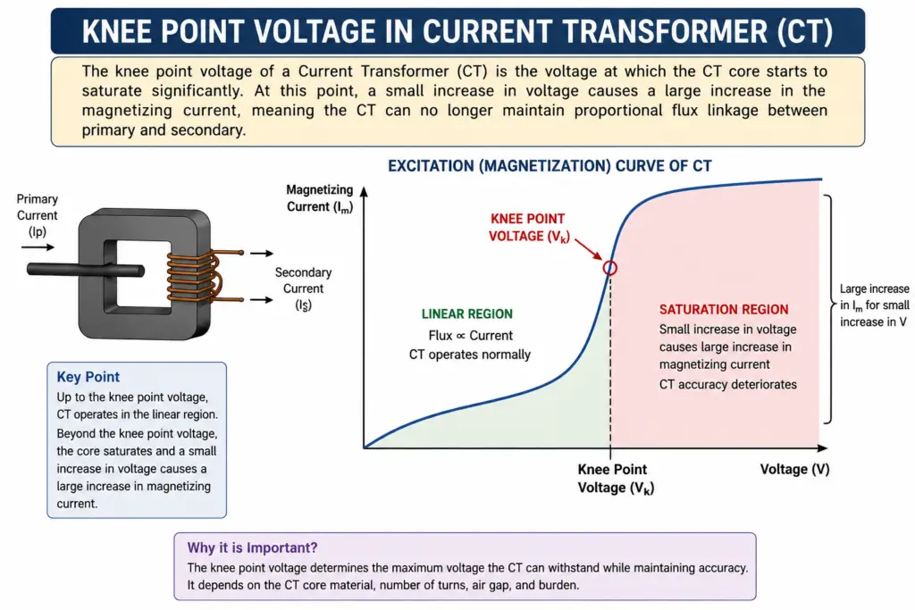
Knee Point Voltage of Current Transformer (CT)
The knee point voltage of a Current Transformer (CT) is the voltage at which the CT core starts to saturate significantly. At this point, a small increase in voltage causes a large increase in the magnetizing current, meaning the CT can no longer maintain proportional flux linkage between primary and secondary.
In simple terms, it is the point on the magnetization curve where the CT begins to lose its linear behavior. This parameter is especially important in protection CTs, particularly PS class CTs used in differential protection systems.
Below the knee point voltage, the CT operates accurately with minimal error. Above it, the core enters saturation, and the output current becomes distorted. Therefore, the knee point voltage defines the maximum usable voltage for accurate protection performance.
Knee point voltage is determined from the excitation (magnetization) curve of the CT. It is usually specified as the point where a 10% increase in voltage causes a 50% increase in excitation current (as per standard definitions).
The calculation of knee point voltage of a CT is based on excitation test data and CT secondary resistance and burden values.
It is critical in ensuring CT stability during fault conditions, especially in high-reliability systems like transformers and generators.
CT Burden (Current Transformer Burden)
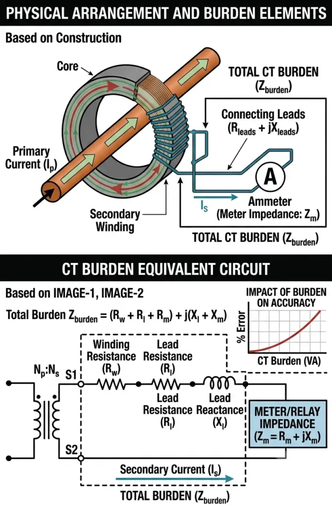
The CT burden refers to the total load connected across the secondary winding of a Current Transformer (CT). It is the amount of impedance that the CT has to supply current to while maintaining accurate performance. Burden is usually expressed in VA (volt-amperes) at a specified secondary current, typically 1 A or 5 A.
The burden includes the resistance of connected devices such as meters, relays, wiring, and the CT secondary winding itself. If the burden is too high, the CT may not perform accurately and can enter saturation, leading to measurement errors or protection failure.
CTs are designed with a specified rated burden, such as 5 VA, 10 VA, or 15 VA. The CT must always operate within this limit to ensure proper accuracy class performance.
In simple terms, CT burden is the “load” that the CT secondary must supply, and it directly affects the accuracy and stability of the system.
The calculation of CT burden is done by summing the impedance of all connected devices and wiring on the secondary side.
CT Errors (Current Transformer Errors)
Current Transformer (CT) errors refer to the deviations between the actual primary current and the scaled secondary current produced by the CT. These errors affect the accuracy of measurement and the reliability of protection systems in electrical power networks.
There are mainly two types of CT errors: current ratio error and phase angle error.
1. Current Ratio Error
Current ratio error occurs when the actual transformation ratio of the CT is not exactly equal to the rated ratio. This means the secondary current is not perfectly proportional to the primary current. It is mainly caused by excitation current required for core magnetization.
2. Phase Angle Error
Phase angle error is the difference in phase between the primary current and the reversed secondary current. This error is important in power measurement applications because it affects power factor and energy calculation accuracy.
CT errors are influenced by factors such as burden, core material, saturation, and operating conditions. Increasing burden or operating near saturation can significantly increase these errors.
Proper design and selection of the Current Transformer helps minimize CT errors and ensures accurate metering and reliable protection system performance.
CT Grounding (Current Transformer Grounding)
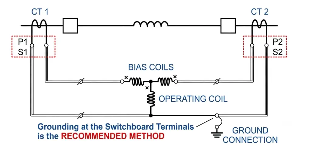
Current Transformer grounding refers to the practice of connecting one point of the secondary winding of a Current Transformer (CT) to earth (ground). This is an important safety and protection measure used in electrical power systems to ensure safe operation of metering and protection circuits.
In a CT, the secondary winding is electrically isolated from the primary, but it can still develop high voltage under fault conditions or if the secondary circuit is accidentally opened. Grounding one terminal of the secondary helps stabilize the voltage and prevents dangerous potential build-up.
Typically, the CT secondary is grounded at a single point only. This avoids circulating currents and ensures proper operation of relays and meters. Double grounding or multiple grounding points should be avoided as it can lead to measurement errors and malfunction of protection systems.
Current transformer grounding also protects personnel and equipment by ensuring that any fault or induced voltage is safely discharged to earth.
CT Saturation (Current Transformer Saturation)
CT saturation is a condition in which the core of a Current Transformer (CT) is unable to carry additional magnetic flux in proportion to the primary current. When this happens, the CT output no longer remains linear, and the secondary current becomes distorted.
In normal operation, the CT core produces a magnetic flux proportional to the primary current, and the secondary current accurately reflects this relationship. However, during high fault currents or excessive burden conditions, the core reaches its magnetic limit. Beyond this point, even if the primary current increases, the secondary current does not increase proportionally.
This leads to measurement errors and incorrect relay operation, which is critical in protection systems. Saturation is more likely to occur when the CT operates near or beyond its rated burden, or when the fault current exceeds its design limit.
CT saturation is particularly important in protection CTs, as it can affect the performance of relays during fault conditions. Proper selection of Accuracy Limit Factor (ALF), correct burden, and suitable core design helps minimize saturation effects.
Why CT Secondary Should Never Be Left Open
The secondary winding of a Current Transformer (CT) should never be left open-circuited while the primary is energized. This is one of the most important safety rules in CT operation.
When the CT secondary is open, no current flows in the secondary winding. As a result, the primary current produces an excessive magnetic flux in the core because there is no opposing secondary ampere-turns to balance it. This leads to a rapid increase in core flux, which induces a very high voltage across the secondary terminals.
This high induced voltage can become dangerous for both equipment and personnel. It may cause insulation failure, overheating, or even electrical shock hazards. In some cases, it can permanently damage the CT winding or connected terminals.
Additionally, the core may enter deep saturation and develop excessive heating, further reducing the life and reliability of the CT.
To avoid this condition, the CT secondary should always be kept short-circuited or connected to a proper burden (meter/relay) whenever the primary is energized.
Core Balance Current Transformer (CBCT)
A Core Balance Current Transformer (CBCT) is a special type of current transformer used for earth fault protection. It works by measuring the vector sum of all phase currents, which becomes zero under normal conditions. Any imbalance indicates a leakage or fault current.
CBCTs are widely used in:
- Earth leakage protection systems
- Motor protection
- Feeder protection systems
Difference Between Current Transformer (CT) and Potential Transformer (PT)
The main difference between CT and PT is that a Current Transformer (CT) is used to step down high current to a safe, measurable value, whereas a Potential Transformer (PT) is used to step down high voltage to a standardized low voltage for measurement and protection purposes. Both CT and PT are types of instrument transformers used in electrical power systems for accurate metering and protection.
A CT is always connected in series with the power line and provides a proportional low current output, typically 1A or 5A. In contrast, a PT is connected in parallel across the line and delivers a reduced voltage output, usually around 110V.
Both instrument transformers play a crucial role in safely monitoring high-voltage power systems, but they differ in the electrical quantity they measure and their method of connection.
Ratings & Specifications of Current Transformer (CT)
The ratings and specifications of a Current Transformer (CT) define its operating limits, performance characteristics, and suitability for a particular application in metering or protection systems. These parameters ensure safe, accurate, and reliable operation in electrical power networks.
1. Primary and Secondary Current Rating
The primary rating indicates the maximum current the CT can carry, such as 100 A, 200 A, 1000 A, etc. The secondary rating is standardized as 1 A or 5 A, which is used for measuring instruments and relays.
2. CT Ratio
The CT ratio represents the relationship between primary and secondary current, for example 200/5 A or 1000/1 A. It determines the scaling of high current into a measurable value.
3. Burden (VA Rating)
Burden defines the total load connected to the CT secondary winding. It is specified in VA (volt-amperes), such as 5 VA, 10 VA, or 15 VA.
4. Accuracy Class
Accuracy class indicates how precisely the CT reproduces primary current. Metering CTs use classes like 0.2, 0.2s, 0.5, 1, while protection CTs use 5P10, 10P20, etc.
5. Frequency and Insulation Level
CTs are designed for standard system frequencies like 50 Hz or 60 Hz and are rated for specific insulation levels based on system voltage.
In summary, the Current Transformer ratings and specifications ensure proper selection, accurate measurement, and reliable protection in electrical systems.
Testing & Maintenance of Current Transformer (CT)
The testing and maintenance of a Current Transformer (CT) are essential to ensure its accuracy, safety, and reliable operation in both metering and protection systems. Regular testing helps detect insulation issues, ratio errors, and core saturation problems before they lead to system failures.
1. Insulation Resistance Test
This test checks the health of CT insulation between primary, secondary, and earth. A low insulation resistance indicates moisture, aging, or insulation damage.
2. Polarity Test
The polarity test ensures correct direction of current flow between primary and secondary terminals. Incorrect polarity can lead to relay maloperation and wrong energy measurement.
3. Ratio Test
The CT ratio test verifies whether the actual transformation ratio matches the rated value (e.g., 200/5 A). Any deviation may indicate winding or core issues.
4. Burden Test
This test ensures that the connected load on the CT secondary is within the rated burden limit. Excess burden can reduce accuracy and cause saturation.
5. Visual and Mechanical Inspection
Regular inspection checks for loose connections, overheating signs, cracks in insulation, and terminal condition.
Proper testing and maintenance of the Current Transformer ensures long-term reliability, accurate measurement, and safe operation in electrical power systems.
CT Selection Guide (Current Transformer Selection)
The selection of a Current Transformer (CT) is a critical step to ensure accurate measurement, proper protection, and safe operation in electrical power systems. A correctly selected CT improves system reliability and prevents errors in metering and relay operation.
1. Determine System Current
The first step is to identify the maximum load current in the system. The CT primary rating should be slightly higher than the normal operating current to avoid saturation during normal conditions.
2. Choose CT Ratio
Select an appropriate CT ratio such as 100/5, 200/5, 1000/1, based on system current and instrument requirement. The ratio should match both metering and protection needs.
3. Select Secondary Current
Standard secondary currents are 1 A or 5 A. Long cable runs generally prefer 1 A CTs to reduce voltage drop and burden.
4. Decide Accuracy Class
For metering, use accuracy classes like 0.2, 0.5, or 1.0. For protection, use classes like 5P10, 10P20, or PS class CTs depending on application.
5. Check Burden Rating
Ensure the CT burden (VA rating) is higher than the total connected load of meters, relays, and wiring.
6. Consider ALF and ISF
Protection CTs require proper Accuracy Limit Factor (ALF), while metering CTs require appropriate Instrument Safety Factor (ISF).
7. System Voltage and Insulation Level
The CT must match the system basic insulation voltage to ensure safe operation under all conditions.
Proper selection of the Current Transformer ensures accurate measurement, reliable protection, and long-term system stability.
Applications of Current Transformer (CT)
The Current Transformer (CT) is widely used in electrical power systems for measurement, monitoring, and protection. It safely steps down high alternating current to a low, standardized value that can be used by instruments and protective devices.
1. Power System Protection
CTs are extensively used in protection relays for detecting faults such as short circuits, overloads, and earth faults. They help in tripping circuit breakers during abnormal conditions to protect equipment and maintain system stability.
2. Energy Metering
In commercial and industrial installations, CTs are used with energy meters to measure electrical consumption accurately. They allow safe monitoring of high currents without direct connection to the main supply.
3. Substations and Switchgear
CTs are installed in substations and switchgear panels for continuous monitoring of current in transmission and distribution networks. They play a key role in system control and protection coordination.
4. Industrial Applications
In industries, CTs are used for load monitoring, motor protection, and power quality analysis. They help in optimizing energy usage and preventing equipment damage.
5. Power Generation Systems
CTs are used in generators and power plants for monitoring output current and ensuring proper protection of expensive electrical equipment.
Advantages of Current Transformer (CT)
The Current Transformer (CT) offers several important advantages in electrical power systems, making it an essential component for measurement and protection applications.
1. Safe Measurement of High Current
CTs allow safe measurement of very high currents by stepping them down to a standardized low value (1 A or 5 A). This protects instruments and operators from direct exposure to high voltage and current.
2. Electrical Isolation
CTs provide complete electrical isolation between the high-voltage power circuit and the measuring instruments. This improves safety and reduces the risk of damage to sensitive equipment.
3. Standardized Output
The secondary output of CTs is standardized, making it easy to connect with various meters, relays, and protection devices without modification.
4. Accurate Monitoring
CTs offer good accuracy in both metering and protection applications when selected correctly. This ensures reliable energy measurement and fault detection.
5. Compact and Easy Installation
Modern CTs are compact in design and can be easily installed in switchgear, panels, and substations without requiring major modifications.
6. Cost-Effective Solution
CTs reduce the need for expensive high-current measuring instruments by allowing the use of standard low-current devices.
Disadvantages of Current Transformer (CT)
Although the Current Transformer (CT) is widely used in power systems, it also has some limitations that must be considered during design and operation.
1. Open Secondary Hazard
One of the biggest disadvantages is that the CT secondary should never be open-circuited while the primary is energized. If left open, it can produce dangerously high voltage, which may damage insulation or cause safety risks.
2. Saturation Problem
During high fault currents, the CT core may saturate. This leads to distorted secondary current and can affect the performance of protective relays and metering accuracy.
3. Limited Accuracy Range
CTs are accurate only within a specified range of current and burden. Outside this range, measurement errors increase significantly.
4. Burden Sensitivity
CT performance is highly dependent on the connected burden. Excess burden can reduce accuracy and cause early saturation.
5. Cost for High Accuracy CTs
High-precision CTs used in protection and metering applications can be expensive, especially PS class or high ALF CTs.
6. Core Losses and Heating
CT cores experience iron losses and heating during continuous operation, which may affect long-term performance.
Conclusion
The Current Transformer (CT) is an essential instrument transformer used in modern electrical power systems for safe and accurate measurement of high alternating currents. It plays a key role in both metering and protection applications by stepping down high primary current to a standardized low value suitable for instruments and relays.
From basic construction and working principle to advanced concepts like accuracy class, burden, ALF, saturation, and knee point voltage, the CT ensures reliable system monitoring and fault protection when properly selected and installed. However, correct handling is crucial, especially ensuring that the secondary is never left open-circuited during operation to avoid dangerous high voltages.
A well-designed and properly rated CT improves system safety, measurement accuracy, and protection reliability in power networks. Therefore, understanding its types, specifications, errors, and operating limits is important for engineers and technicians working in electrical systems.
In summary, the Current Transformer is a vital component that ensures efficient monitoring, accurate energy measurement, and dependable protection across generation, transmission, and distribution systems.
Read Next:
- Core Balance Current Transformer(CBCT)
- Types of Current Transformers (CT): Classification, Working, Applications
- Why CT Secondary Should Never Be Open?
- Difference between Current Transformer(CT) & Potential Transformer(PT)
- Current Transformer Construction, Phasor and Errors
- Instrument Safety Factor of Current Transformer
- What is meaning of 5P20 in current transformer?
- Current Transformer Secondary Grounding
- Accuracy Class Of Current Transformer
- What is Knee Point Voltage of a Current Transformer (CT)?
- CT Ratio Calculator & CT Ratio Calculation Formula
- CT Saturation- Reasons, Problems & Mitigation