The accuracy class of a CT refers to the permissible error limits of the CT over a specified range of conditions. It ensures that the measurement or protection device connected to the CT receives an accurate representation of the primary current. The classes are designated by standard organizations such as IEC (International Electrotechnical Commission) and ANSI (American National Standards Institute).
Current transformers (CTs) measure electrical parameters such as current (amperes), power, and energy. They also play a crucial role in detecting fault conditions by measuring fault currents and triggering the upstream breaker to prevent damage to the electrical network. From a protection standpoint, the accuracy class of a current transformer is essential, as it ensures the reliability and security of the electrical network.
This article describes the accuracy classes of different current transformers for metering and protection.
Classes of CT
Three classes of CTs are widely used in electrical networks. These are-
- Metering Class CT
- Protection Class CT
- Special Protection Class CT
We will discuss in detail the classes of CTs and their measurement accuracy.
Metering Class CT
Measurement CTs are used for metering and instrumentation purposes are called metering class CTs. Their crucial role is to measure current accurately with minimal error. The accuracy class parameter is vital for metering CTs.
Accuracy Class of Metering CT
The accuracy class is typically denoted by a number representing the percentage error allowed at the rated current.
According to IEC, the standard accuracy classes are 0.2, 0.5, 1, 3, and 5. CT with accuracy classes of 0.1, 0.2, 0.5, and 1.0 is used to measure electric current. CT accuracy class and error limits are shown in the below table,.
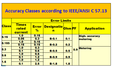
0.1 and 0.2 accuracy class CT: These CTs are used in a revenue metering application. 0.2 class metering CT means the CT functions within the specified accuracy limit at 100 % and 120 % of the rated CT current, and the accuracy limit error is 0.2 %. The CT operates in the linearity zone of the magnetization curve, and it consumes a very low magnetizing current. The 0.3 class CT reads 0.997 to 1.003 at 100% rated current, and at 10% current, the CT reads in the range of 0.994 to 1.006.
Class 1: These CTs are accurate to within 1% of the rated current. They are commonly used in general metering applications.
Class 3: These CTs allow up to 3% error and are used where high accuracy is not as critical.
Class 0.2s and 0.5s: These CT classes are used in revenue metering applications. The 0.2 s and 0.5s class CT have a ratio error of 0.2 % for current from 20 to 120% of the rated current. The ratio and phase angle error 0.2s -0.5s metering class CT are shown in the table below.
| Accuracy Class | ±Percentage Current (Ratio) Error at Percentage of Rated Current Shown Below | ±Phase Displacement at Percentage of Rated Current Shown Below | |||||||||||||||
| Minutes | Centiradians | ||||||||||||||||
| 1 | 5 | 20 | 100 | 120 | 1 | 5 | 20 | 100 | 120 | 1 | 5 | 20 | 100 | 120 | |||
| 0.2S | 0.75 | 0.35 | 0.2 | 0.2 | 0.2 | 30 | 15 | 10 | 10 | 10 | 0.9 | 0.45 | 0.3 | 0.3 | 0.3 | ||
| 0.5S | 1.5 | 0.75 | 0.5 | 0.5 | 0.5 | 90 | 45 | 30 | 30 | 30 | 2.7 | 1.35 | 0.9 | 0.9 | 0.9 | ||
The ratio and phase angle error of 0.1 -1.0 class metering class CT are shown in the table below.Accuracy Class ±Percentage Current (Ratio) Error at Percentage of Rated Current Shown Below ±Phase Displacement at Percentage of Rated Current Shown Below Minutes Centiradians 5 20 100 120 5 20 100 120 5 20 100 120 0.1 0.4 0.2 0.1 0.1 15 8 5 5 0.45 0.24 0.15 0.15 0.2 0.75 0.35 0.2 0.2 30 15 10 10 0.9 0.45 0.30 0.30 0.5 1.50 1.75 0.5 0.5 90 45 30 30 2.7 1.35 0.9 0.9 1.0 3.0 1.5 1.0 1.0 180 90 60 60 5.4 2.7 1.8 1.8
The core of a metering CT becomes saturated when the current exceeds its rated value. This saturation limits the current within the device, protecting the connected metering equipment from overloading during fault conditions. The key features of metering CTs are as follows.
- High accuracy in a smaller range
- Less core material is required
- This leads to lower saturation voltages
The metering CT has less core material than the protection class CT. The metering CT specification is written as 0.3 B 1.8. The first number is the current transformer accuracy class, B is the metering class, and 1.8 is the maximum burden connected to the CT.
The other parameters of metering class CT are as follows.
Important Parameters of Metering Class CT
CT Ratio: The current transformation ratio(CTR) is the ratio of the input current to the output current. A current transformer of 300/5 CTR means that if the primary current is 300 Amps, the secondary current is 5 Amps.
CT Burden: The burden of the current transformer is expressed in VA. The total burden should be considered when CT is used for measuring or protection purposes. To calculate the total burden of the secondary circuit of the CT, the total resistance of the secondary side of the CT should be considered. The secondary winding of CT is connected to the measuring equipment or protection circuit through pilot wires. The total resistance of the secondary circuit is the sum of CT secondary winding resistance, connecting wires resistance, and the resistance of the relay/meter.
For example, suppose the relay resistance is 0.1 ohm. In that case, the connecting wire resistance is 0.2 ohm, the secondary winding resistance of CT is 0.1 ohm, and the total resistance of the secondary circuit is 0.1+0.2+0.1=0.4 ohm. If the rated secondary current of the CT is 5 Amp, then the secondary voltage is (Is*Rburden)= 0.4*5=2 volts. The burden of the current transformer is =Is*Vs= 5*2=10 VA.
Rating Factor: The multiple of Rated Current to which the CT can maintain its accuracy is called the rating factor of CT. Typical rating factors are 1, 1.5, 2, 3, and 4. For example, 500/5A CT with RF 2 CT will maintain its accuracy certification up to 1000A.
Protection Class CT
Protection class current transformers (CTs) are designed to provide accurate current measurements during abnormal conditions, such as faults, to ensure the proper operation of protective relays and circuit breakers. The accuracy class of a protection CT is crucial for the reliability and effectiveness of the protection system.
Protection class CT is connected to the protection relay that gives a tripping command to the circuit breaker at the time of fault condition. The protection class CT has the following features.
- CT is required to perform in fault current
- Moderate accuracy over a broader range
- More core material is needed
At the time of the fault, the primary current of CT increases abnormally high, and the core can get magnetized above its rated capacity. Whatever fault current flows in the circuit can’t be reflected in the secondary side of the CT. This phenomenon is known as CT saturation. If CT gets saturated at the time of the fault, the protection relay will not operate.
Therefore, ensuring that the protection relay must operate at the time of fault is very important. The protection class CT is designed to take care of fault current. The Protection CT requires an Accuracy Limit Factor (ALF) to ensure this. Accuracy Limit Factor (ALF) is the multiple of rated currents up to which CT will operate, complying with the accuracy class requirement.
Accuracy Classes of Protection Class CT
Protection CTs have specific accuracy classes indicating their performance under fault conditions. These classes include:
- Class 5P: Maximum permissible error of 5% at the accuracy limit primary current. 5P10 class CT- If the primary current is ten times the rated primary current of the CT, the CT will function perfectly within the accuracy limit of 5 %.
5P20 Class CT-A 5P20 CT has an Accuracy limit of 5% at 20 times rated current (Accuracy Limit Factor). This CT’s current transformer’s accuracy class at rated current is 1%. - Class 10P: Maximum permissible error of 10% at the accuracy limit primary current.
Marking on CT—The accuracy class of the protection class current transformer is written after the CT’s rated VA, E.g.
- 10VA5P10
- 15VA10P10
- 30VA5P20
C-Rating of Current Transformers (CTs)
C-rated current transformers (CTs) are commonly used in North America and follow the ANSI/IEEE C57.13 standard. C200 CT means the CT will maintain the 200 volts secondary voltage, and the measuring error of CT is,
– Less than 3% ratio error at rated current
– Less than 10% ratio error at 20 times rated current
– Standard burden 200V/ (5A x 20) = 2Ω
Protection Special(PS) class CT
PS or PX class CT: These CTs are used for differential protection of the generator, motor, and transformer. The manufacturer requires the following parameters for the CT design.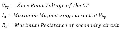
Class PR, TPX, TPY, TPZ: Defined for special protection applications, particularly in systems requiring high precision and stability under dynamic conditions.
Read Next:
Thanks for the post. It helped me understand what the accuracy class of a CT is and why it is used.
Thanks for the valued information. I have learnt greatly from this vital information
U r writing technically sound Contents. Power engineers can understand a lot from ur work…
Hats off to ur team and keep going….
Thanks a lot
Nice content and elaboration sir
very good information. thanks.