This article describes the current transformer – construction, Phasor, and Errors. Current transformers are widely used for measuring high currents. The Current transformer steps down the high value of current to the low value, which the measuring instrument can read.
If 2000 Amperes current is to be read by a meter, it is not possible to read because a small shunt resistance of high power rating in parallel to the galvanometer is required to be used. However, using a small value shunt resistance of a high power rating to read high current directly by the meter is impractical. That is why a current transformer is used to lower the magnitude of the current so that the measuring instrument and protective relay can read the current.
Construction of Current Transformer(CT)
The current transformer has two windings, primary and secondary. The primary winding has fewer turns and is connected in series with the primary circuit. The entire circuit current passes through the primary winding, and it is desirable that the voltage drop across the primary winding must be as low as possible. The current transformer has fewer turns of large cross-sections, and thus, the voltage drop in the primary winding gets reduced to a great extent.
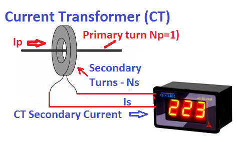
The secondary winding has more turns than the primary winding, which is connected by an ampere meter, energy meter, watt meter, transducer, and protection relay. The secondary winding of the CT must be connected with a low-impedance meter to keep the magnetic flux in the core up to its rated flux capacity.
The flux in the core above the rated capacity causes saturation of the magnetic core, which leads to the complete failure of the current transformer. The CT secondary must not be left open because, in this condition, the flux in the core increases manifold, and it causes CT core saturation.
Based on the construction, there are two types of current transformers- Live Tank CT and Dead Tank CT. In both types of CTs, the core and winding are enclosed in a porcelain structure, and this structure is filled with mineral-insulated oil, which acts as cooling media and provides the required electrical insulation.
Symbol of Current Transformer (CT)

Terminals P1 and P2 show the primary winding of the CT, and terminals S1 and S2 show the secondary winding of the CT. The CT ratio 2000/1 means the secondary current will be 1 ampere if the primary current through the CT is 2000 amperes.
Equivalent Circuit of Current Transformer(CT)
The CT equivalent circuit is given below.

The CT primary has few turns, and it has very little resistance. Rp and Xp, respectively, denote the primary winding resistance and reactance. The secondary winding resistance and reactance are denoted by Rs and Xs, respectively. The magnetization components of the current transformer are Rc and Xm. Rc is responsible for the core loss component, and Xm is the magnetization reactance of CT.
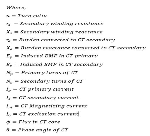
The other CT parameters are given below.
Phasor Diagram of Current Transformer(CT)

The equivalent circuit of the current transformer is similar to that of the power transformer and induction motor. The current transformer has two types of errors.
- Ratio Error
- Phase Angle Error
From the phasor diagram, the CT ratio error and phase angle error can be calculated.
CT Transformation Ratio
CT transformation ratio is calculated as follows. To find the transformation ratio, we need to calculate the primary current Ip, as per the definition, and divide it by the secondary current Is.

The CT transformation ratio of 1000/5 ratio CT is 200.
Ratio Error of Current Transformer
In an ideal current transformer, the primary current (Ip) should equal the multiplication of the secondary current and the turns ratio of CT. However, the secondary current does not vary in the same proportion as the increase in primary current and secondary current is less than the nominal secondary current. The error in the CT due to the difference in the current from its rated nominal ratio is called the current error or ratio error. The ratio error in a current transformer is due to magnetizing current, core loss current, leakage reactance, and burden impedance.
The CT ratio Error is defined as the per unit deviation in transformation ratio from its nominal ratio. Ratio error is expressed in percentage.

CT Ratio Error Formula Derivation
Let us consider the part of the phasor of our importance for calculating Ip as shown below.
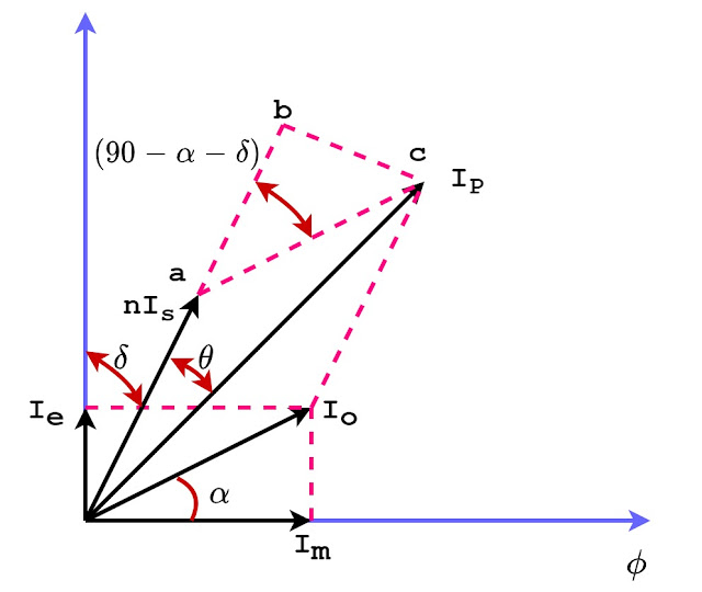
From the above phasor, the primary current Ip is the phasor sum of nIs and I0. The CT primary current Ip can be calculated using the vector addition formula.

The magnetizing current Io is very small compared to the primary current Ip. Therefore, the above expression can be simplified as follows.
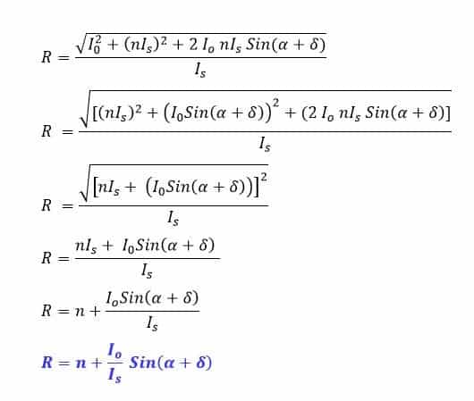
From the above expression, it is clear that the transformation ratio is not equal to the turn ratio. The transformation ratio and turn ratio will be equal if α=0 and δ=0.This condition can be achieved if the core loss is equal to zero and the burden is purely resistive. This is an ideal condition. However, this condition is practically impossible.
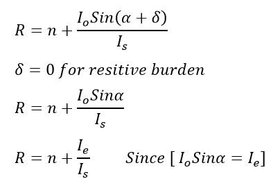
Ratio Error of Current Transformer for Resistive Burden
Since the burden of the CT is generally resistive. Therefore, the power factor of the burden is unity, and hence δ=0
Phase Angle Error of the Current Transformer
The primary and secondary current of the CT should be out of phase, meaning the phase angle between the primary and secondary must be 180 degrees. Any deviation in the phase angle from 180 degrees is called the phase angle error of the CT.
The phase angle of the current transformer is defined as the angle between the primary current Ip and secondary current Is. In the above phasor diagram, θ is the phase angle.
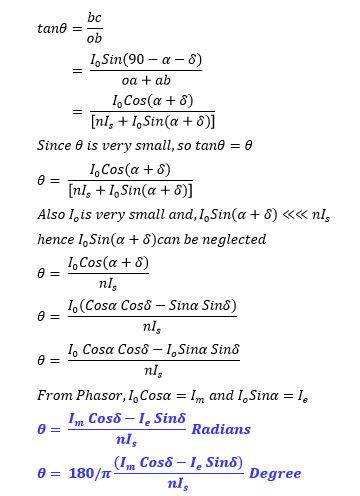
CT Phase Angle Error Formula Derivation
Consider the right angle triangle ABC in the above phasor diagram.
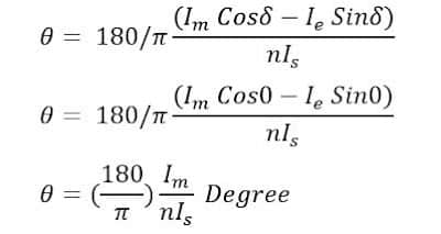
Phase Angle Error of Current Transformer For Resistive Burden
The phase angle between the primary and secondary of the current transformer must be 180 degrees. The primary and secondary current must be out of phase. The phase angle error is the deviation in the phase angle of the primary and secondary current. The phase angle between the primary and secondary current of the CT is denoted by angle θ.
Since the CT burden is generally resistive, the power factor of the burden is unity, and hence δ=0. The following expression gives the phase angle error of CT.
FAQs on CT Ratio and Phase Angle Error
Ratio error in a CT is the difference between the actual transformation ratio and the nominal (or rated) transformation ratio. It can be expressed as a percentage of the nominal ratio.
Ratio error is calculated using the formula:
Ratio error (%)= (Rated Ratio- Actual Ratio)/Actual Ratio X 100
Ratio error can be caused by several factors, including:
– Magnetic losses in the core.
– Magnetizing current
– Imperfections in the CT winding.
– Leakage flux.
– Burden connected to the secondary winding.
Phase angle error is the angular difference between the primary and secondary currents. Ideally, this angle should be 180 degrees, meaning the primary and secondary currents should be out of phase.
Phase angle error is typically measured using a phase angle meter. This device compares the phase relationship between the primary and secondary currents and provides the phase angle difference.
Factors that affect phase angle error include:
– Core material and design.
– Magnetic properties of the core.
– Connected burden to the secondary winding.
– Operating frequency.
– Excitation current of the CT.
Minimizing phase angle error is crucial for accurate power measurement and protection. High phase angle errors can lead to incorrect readings in metering applications and malfunctioning of protection relays.
To minimize these errors, consider:
– Using high-quality core materials.
– Ensuring the CT operates within its specified burden.
– Proper design and manufacturing techniques.
– Regular calibration and testing of the CT.
CT accuracy is often defined by standards such as:
– IEC 60044-1 (Instrument Transformers – Part 1: Current Transformers)
– ANSI/IEEE C57.13 (Standard Requirements for Instrument Transformers)
The burden is the load connected to the CT’s secondary winding, typically expressed in VA (volt-amperes). The performance, including ratio and phase angle error, can be significantly affected by the burden. Operating within the specified burden ensures optimal accuracy.
CT ratio and phase angle accuracy are critical for the following:
– Revenue metering for accurate billing.
– Protective relaying for reliable operation of protection devices.
– Power quality monitoring to ensure system stability.
CTs should be tested periodically, typically once every 5 to 10 years, or according to the manufacturer’s recommendations and industry standards. More frequent testing may be required in critical applications or harsh environments.
Related Articles:
hello how we can measure or calculate ( Im) in ct to calculate phase angle error.
thanks.