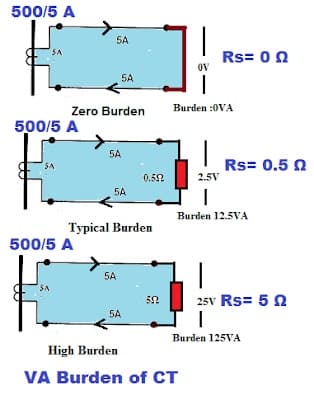
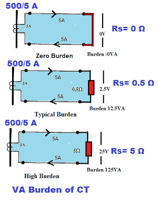
The burden of the current transformer is expressed in VA. The total VA burden should be considered when CT is used for measuring or protection purposes.
The total resistance of the secondary circuit of CT, known as a burden, is the sum of resistances of CT secondary winding, connecting wires(lead resistance), and the resistance of the relay/meter.
Thus, the total VA burden of the CT can be calculated by adding the VA burden of the following.
- The VA burden of the measuring equipment like protection relay and measuring instruments
- The VA burden of the leads connected between the current transformer and the relay/measuring meter
- The secondary resistance of the current transformer
VA Burden of meters and the protection relay:
The VA burden of the energy meters, voltmeter, ammeter, power factor meter, and protection relay is mentioned in the catalog of the instrument. The electronic meters and the numeric relays have less VA burden than the analog meters and the electromechanical relay.
While designing the protection system or measurement system, the VA burden of all the measuring instruments and protection relays must be considered for building a reliable measurement and protective system.
The VA burden of various electrical equipment is given below.
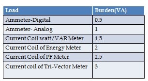
VA Burden of the meter or the protection relay can be taken from the equipment manufacturer’s datasheet.
VA Burden of the connecting lead wires:
The VA burden of the lead wires can be calculated by following a mathematical formula.
Lead Wire Burden in VA= I2 * 2 D/ (CS x 57)
Where: I = Secondary Current in Amps
D = Lead wire distance in meters.
CS =Cross section area of lead wire.
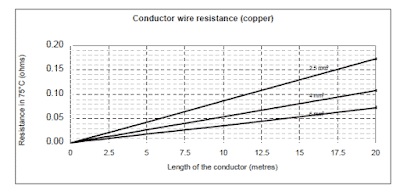
The thicker the wire, the lesser the resistance, and as a result of the larger cross-sectional area of the conductor, the VA burden of the connecting wire will be less. The measuring instrument or the protection relay must be installed as near the current transformer as possible so that the lead resistance can be minimized. The resistance of the conductor is temperature dependent, and the resistance is measured at 75°C.
| Read More : Correction of Resistance at 75°C |
The resistance of the copper wire of different cross-sectional areas at 75°C is given below.
The lead wire resistance can be calculated for the 6-wire and 4-wire configurations. The three sets of CT connections can be brought in the relay or metering panel by two methods.
- The 2-wires of each CT can be brought in the panel. The six wires of the three CTs can be connected to the meter/ protection relay.
- The common point can be made at the test terminal block, and the four wires can be brought into the relay/metering panel.
The wiring scheme is given below.
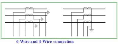
If the distance between CT and the relay or metering panel is 10 meters, the total distance is 10 x 2 = 20 meters for a 6-wire connection. However, the distance for the 4-wire connection when one wire is used as a return wire is equal to 1.2 x 10 =12 meters. This rule is applicable to three-phase connections.
| Read More : Accuracy Class of Current Transformer |
The resistance of the secondary of the CT:
The secondary of the current transformer has many turns of the copper wire, and the internal resistance of the CT is taken into account while calculating the VA burden of the CT.
VA Burden of Current Transformer:
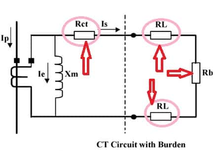
Thus, the burden of the current transformer depends on the internal resistance of the CT, leads resistance and the resistance of the relay.
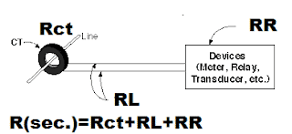
To calculate the total burden, you need to consider:
- The resistance of the CT secondary winding (RCT).
- The resistance of the wiring- Leads Resistance (RL).
- The impedance of the connected devices (e.g., meters, relays) (RR).
The total burden (Rsec) is then the sum of these impedances:
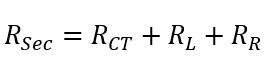
Where,
RCT – Resistance of the secondary of the CT
RL – Lead Resistance
RR – Relay or meter resistance
RSec= Total CT burden in Ohm
If the CT secondary current is I, the CT burden in VA can be calculated using the formula below.
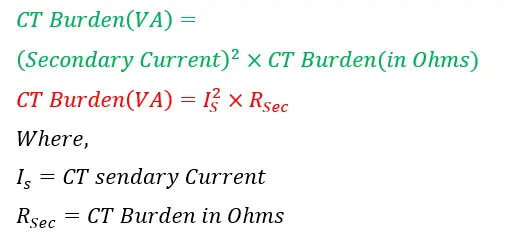
CT burden Calculation:
Example: If the relay resistance is 0.2 Ω, connecting wires resistance is 0.2 Ω, and the secondary winding resistance of CT is 0.2 Ω. The total resistance of the secondary circuit is 0.2+0.2+0.2=0.6 Ω.
The total burden of the CT is 0.6 Ω.
If the rated secondary current of the CT is 5 Amp. The secondary voltage is 0.6*5= 3 volts,
The burden of the current transformer in VA is ;
CT (VA) = CT rated secondary current x CT Secondary Voltage
=5*3=15 VA.
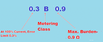
CT Burden Ratings According to IEC/ANSI Standard:
The burden of the CT is the resistive impedance of the secondary circuit of the CT. The burden of the CT can be expressed in VA or impedance. The IEC standard specifies the CT burden in VA, and typically, burden ratings are 1.5 VA, 3 VA, 5 VA, 10 VA, 15 VA, 20 VA, 30 VA, 45 VA, and 60 VA. The ANSI standard specifies the CT burden in Ω, and typically CT burden ratings are B-0.1, B-0.2, B-0.5, B-1.0, B-2.0, and B-4.0. The CT of B-0.1 will maintain the stated accuracy with up to 0.1 Ω on the secondary circuit.
Why is CT burden data important for the protection system?
The reliability of the protection system depends on the operation of the CT below the saturation level on the B-H curve. The knee point voltage changes with a change in the burden of the CT, so the burden of the CT must be calculated during the protection system’s design.
| Read More – Calculation of Knee Point Voltage of CT |
How is the operating Voltage of CT affected by changes in the burden of CT?
The operating voltage of the current transformer changes with a change in the burden of CT. If the protection CT goes defective, the new CT must be checked for its rated burden because the increased burden will cause the CT to operate at a voltage above the normal voltage of CT on the magnetization curve of CT, and if the CT operates at knee point voltage of BH curve during fault with CT increased burden, the protection relay may not operate. The working of CT near the knee point voltage may cause CT saturation during fault.
If the burden of CT increases, the net magnetic flux flowing through the CT core will increase because the secondary current decreases with an increase in CT burden, and the core of the CT will get heated up due to core saturation, which may cause permanent failure of the CT.
When the circuit burden gets too large, the CT secondary voltage becomes distorted. This is because the CT is beginning to have a flux density much greater than normal operation. The CT excitation voltage also increases above normal voltage with an increase in the CT burden, and it may cause CT core saturation.
Wow, well explained and easy to understand.
"If the distance between CT and the relay or metering panel is 10 meters, the total distance is 10 x 2=20 meters for 6-wire connection. however the distance for the 4-wire connection when one wire is used as return wire is equal to 1.2 x 10 =12 meters. This rule is applicable for three phase connection."
HOW THE LENGHT BE 12 METER @ THIS CASE
" the 4-wire connection when one wire is used as return wire is equal to 1.2 x 10 =12 meters"
Very much happy, you really helped me
how to calculate burden resistor value of CT , with below details bus bus bar CT – ziegler ZIS 15.80S – 2500/5 A
If the CT rating is 5VA and sec current is 5amp then the Max resistance of cable will be 0.2ohm
According to this have to select cable size to use in ct.
Low burden CT preferable?