Hartley oscillator is an electronic oscillator in which the oscillator’s frequency is determined through a tuned circuit of inductors and capacitors. It belongs to the class of LC (inductor-capacitor) oscillators.
The invention of the Hartley oscillator circuit was made in the year 1915 by Ralph Hartley, an American engineer. It is one of the earliest oscillator designs.
This article overviews the Hartley Oscillator and explains how it works.
This oscillator is a type of harmonic oscillator that generates continuous sinusoidal waveforms at a specific frequency.
Hartley Oscillator Circuit Diagram
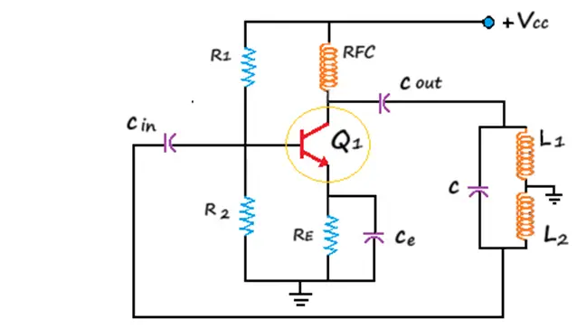
In Hartley Oscillator Circuit RFC (Radio Frequency Coil) is used in circuits; their primary purpose is not to provide isolation between AC and DC operation. Instead, RFCs are typically used to block RF signals while allowing DC to pass through.They do have high reactance at high frequencies, which can be useful in oscillator circuits, but their role is not mainly about AC/DC isolation.
During high frequencies, the reactance value of the choke is very high, so it is considered an open circuit; while its reactance at DC is negligible (nearly zero). Therefore, it does not affect DC biasing. When the power is turned on, the transistor conducts, which increases the collector current. Due to this, capacitor C1 starts charging. After charging, C1 discharges through coil L1.
Due to the charging and discharging process within the tank circuit, a series of damped oscillations, often referred to as resonant oscillations, occur. These oscillations are then coupled to the base of transistor Q1, where they are converted into an amplified signal through the emitter and collector of the transistor.
This voltage present at the collector and emitter of the transistor will be in phase with the voltage of the inductor L1. Since the junction of L1 and L2 is grounded, the voltage across inductor L2 will be at a 180° phase difference. Thus, a complete 360° phase shift is achieved through the tank circuit and amplifier, satisfying the condition for sustained oscillation. At lower frequencies (below 360 kHz), higher inductance values are required.
Principle of Hartley Oscillator
The Hartley oscillator operates based on positive feedback and utilizes a tapped inductor with a capacitor to create a resonant circuit, determining its oscillation frequency.
When power is applied to the circuit, the transistor allows current to flow; it enables energy transfer between the inductor and capacitor in the circuit. The inductive coupling between coils (L1 and L2) introduces positive feedback, and when combined with LC components (inductors and capacitors), it results in a self-sustained oscillatory system.
The specific oscillation frequency in such a circuit is determined by the values of the inductors (L1 and L2) and the capacitor (C).
The Hartley oscillator produces radio frequency (RF) waves, which is why it is also known as a radio frequency oscillator. The oscillator’s frequency is determined by the tank circuit, which comprises a capacitor connected in parallel with two inductors in series.
In normal LC (inductor-capacitor) oscillators, the amplitude of oscillations is typically uncontrollable. The Hartley oscillator circuit differs from a typical LC circuit because it employs an LC parallel feedback configuration, resulting in a self-tuning base oscillator circuit.
Hartley Oscillator Working
The circuit diagram of the Hartley oscillator, as described above, demonstrates a stabilizing network consisting of resistors Re and Rc that represent the emitter and collector resistance.
Resistors R1 and R2 form a voltage divider, and they help establish the appropriate bias voltage at the base of the transistor. This biasing scheme is commonly used in common emitter amplifiers.
In the circuit, Co is the output decoupling capacitor, Cin is the input decoupling capacitor, and Ce is the emitter capacitor. Ce serves dual purposes as both the emitter capacitor and the bypass capacitor. It functions to prevent the amplification of AC signals.
Here, L1, L2, and C form the tank circuit. The components (resistors, capacitors, and inductors) of the Hartley oscillator circuit are similar to the common emitter amplifier circuit, they serve different purposes in the oscillator.
Hartley Oscillator Frequency
The Hartley Oscillator frequency is given as
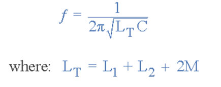
Where L2 and L1 are the inductances of coils 2 and 1, the total cumulative coupled inductance is denoted as LT, and M is the mutual inductance.
By considering two windings, the mutual inductance can be calculated. When the inductor coils are wound on a single core, mutual inductance occurs, which tends to change the behavior of the oscillator circuit. So, both L2 and L1 must be wound into a single-core Hartley oscillator using the OP-AMP.
The Hartley oscillator using an operational amplifier (op-amp) is shown in the figure below. Building this oscillator with Op-Amp has its advantages. The Op-Amp gain can be easily adjusted using the input resistor and feedback resistor.
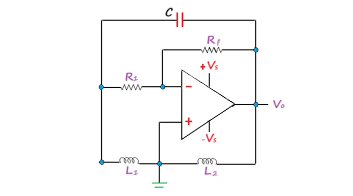
Here, in a transistorized Hartley oscillator, the gain depends on the tank circuit elements L2 and L1. That is, the circuit gain should be equal to or greater than the ratio of L2/L1. However, in the Op-Amp oscillator, the gain depends less on the elements of the tank circuit, so it achieves greater frequency stability.
Hartley Oscillator with OP-AMP
The operation of an op-amp circuit and the transistor version of the Hartley oscillator share some similarities. A feedback circuit is crucial in generating a sine wave in both cases. In the op-amp circuit, this feedback circuit couples with the op-amp section, and the amplifier stabilizes and inverts the resulting wave.
A variable capacitor adjusts the oscillator’s frequency in the tank circuit while maintaining a constant amplitude and feedback ratio within a specified frequency range.
When implemented with an operational amplifier, the frequency of this oscillator remains the same as that of the oscillator discussed previously. When there is mutual inductance between two inductors, L1 and L2, due to the common core between the coils, the voltage transfer ratio of gain becomes Av = (L1+M)/ (L2+M).
Advantages
- Construction of the Hartley oscillator is relatively simple and inexpensive.
- The need for components is very low, even when including threaded coils or fixed inductors.
- The oscillation frequency varies by changing the inductance or using a variable capacitor.
- In some cases, one can replace two separate inductors, L1 and L2, with a single coil of bare wire if the wire meets the required inductance and other electrical specifications.
- The circuit is very simple, and it is not very complex.
- It is possible to generate sinusoidal oscillations with constant amplitude in the Hartley oscillator.
Disadvantages
- It is sensitive to temperature changes and power variations, which can affect the frequency stability of the output signal.
- The disadvantage of the Hartley oscillator is the potential for generating distorted sinusoidal signals due to the presence of harmonics. This distortion is a notable drawback of the Hartley oscillator compared to other oscillator configurations.
- The Hartley oscillator is not typically used as a low-frequency oscillator. This limitation is due to the physical characteristics and constraints of inductors.
Applications
- Due to its wide frequency range, the oscillator is a popular choice for radio receivers to use as a local oscillator.
- The oscillator is suitable for generating oscillations in the radio frequency (RF) range of up to 30 MHz, a standard frequency range for many RF applications.
- The primary function of the oscillator is to generate a sine wave with a specific or desired frequency.
Related Articles: