RTDs are used to measure the temperature of the process, bearings, and motor windings. RTD’s resistance changes with change in temperature and this is used in many applications to measure temperature. RTDs work generally with three RTD wiring configurations – 2-wire, 3-wire, and 4-wire.
Why 2 wire, 3 wire, and 4 wire configurations are required?
RTD is combined with a circuit (present in the transmitter) which gives a voltage drop across RTD with a change in the temperature. This change in voltage is expressed in terms of temperature by a temperature transmitter.
Now to connect the RTD to the transmitter, the cable is the connecting medium. The cable has certain resistance which adds to the RTD resistance. Thus, the total resistance is the sum of the RTD resistance and the lead wire resistance. This causes more voltage drop across the RTD measurement system and as a result causes inaccuracy in measurement.
This is the reason why we use 2 wire, 3 wire, and 4 wire RTD configurations.
RTD Wiring Configurations
There are three different types of RTD wiring configurations available that we use with the RTD sensing circuit.
2 Wire RTD Configuration
- 2 wire configuration is the simplest form of RTD configuration.
- Just add external leads to RTD and connect them to the transmitter.
- We call the 2 wire configuration as serial configuration because both ends of the RTD leads have a serial connection between the RTD and transmitter.
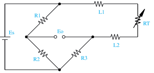
- The above image shows a 2 wire RTD RT with lead wires L1 and L2 connected in a Wheatstone bridge. Es is the supply voltage and Eo is the output voltage. R1, R2, and R3 are 3 other leg resistors of the Wheatstone bridge.
- L1 and L2 directly add to the resistance of RTD causing inaccurate readings.
- RTD resistance = RT (resistance) + L1 (resistance) + L2 (resistance)
- The lead resistance introduces error in temperature measurement.
- 2 wire RTD is the simplest form of RTD configuration, least expensive but also least accurate.
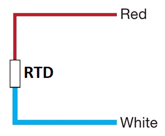
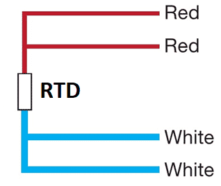
- According to standard IEC-60751, lead wire colors for 2 wire RTD is Red and White
3 Wire RTD
- The 3 wire RTD configuration is the most popular and suitable for temperature measurement in industrial processes and monitoring applications.
- In 3 wire configuration, two wires connect the sensor element to a monitoring device on one side of the sensory element, and one connects it to the other side.
- It is very important to note that all 3 lead wires should be of the same material
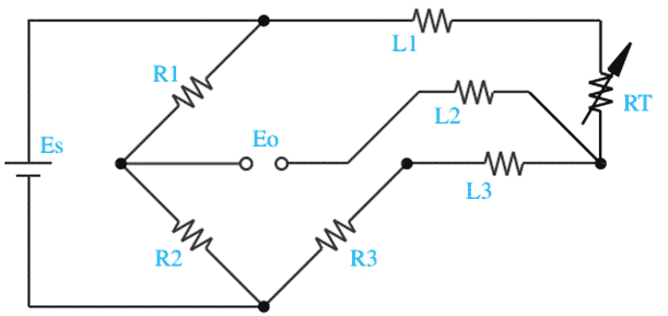
- In the 3 wire RTD configuration, the RTD has three lead wires L1, L2, and L3. Es is the supply voltage and Eo is the output voltage in the Wheatstone bridge. R1, R2, and R3 are 3 other leg resistors in the RTD Wheatstone bridge.
- 3 wire RTD works by calculating the resistance difference between (L1 resistance + L2 resistance + RT) and (L2 resistance + L3 resistance). All 3 lead wires i.e. L1, L2, and L3 have the same resistance.
- The accuracy of temperature measurement using 3 wire RTD configuration is much better because this method eliminates lead wire resistance up to some extent. Therefore, this RTD configuration is most suitable for most temperature measurement applications.
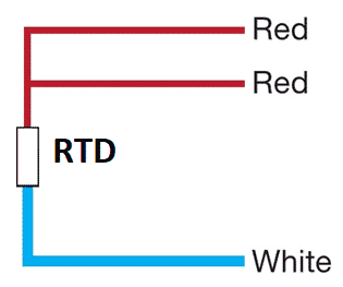
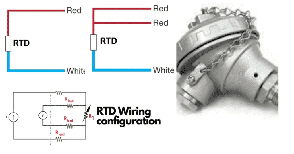
- According to standard IEC-60751, the lead wire colors for 3 wire RTD is Red, Red, and White.
4 Wire RTD
- The 4 wire RTD is the most accurate of all RTD configurations.
- 4 wire RTD not only eliminates the lead wire resistance but also eliminates other resistances added up from the contact points also which 2 wire RTD configuration and 3 wire RTD configuration fail to eliminate.
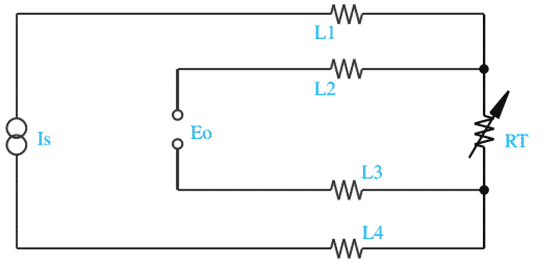
- In 4 wire RTD, the RTD has L1, L2, L3, and l4 lead wires. The current Is is the supply current from a known source and Eo is the output voltage for 4 wire RTD.
- L1 resistance and L4 resistance power the circuit forming L2 resistance, L3 resistance, RTD RT, and voltage sensor. Here simple Ohm’s law is applicable for knowing the true resistance of RTD (RT). The voltage across RTD is E0.
E0= Is*RT.
Thus, the voltage Eo shows the true RTD resistance value. And, thus the 4 wire RTD completely eliminates the lead wire resistance problem. - 4 wire RTDs are most suitable for temperature measurement in laboratories because of their high accuracy requirements.
- According to standard IEC-60751, the lead wire colors for 4 wire RTD is Red, Red and White, and White.
Read Next: