What is an Ideal Transformer?
An ideal transformer is free from all losses. It has zero copper and iron loss and zero leakage flux, and therefore, it is 100% efficient. In an ideal transformer, the output power is equal to the input power. An ideal transformer can not exist in reality.
The transformer has two windings – primary and secondary. The winding has resistance and reactance, so losses occur in a practical transformer. However, an ideal transformer has zero losses and 100 % efficiency, which is an entirely hypothetical condition.
The equivalent circuit of a practical transformer is given below.
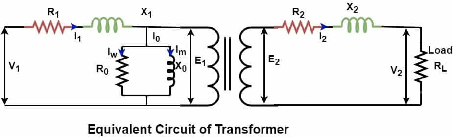
The resistance and reactance of the winding must be as minimal as possible to have low power losses. However, it is only imaginary that winding has zero resistance and reactance.
Properties of an Ideal Transformer
The proprieties of an ideal transformer are as follows.
- Zero Copper loss – The copper loss of an ideal transformer is zero because the winding resistance of the primary and the secondary is zero. This means that both windings have zero resistance, and thus, copper loss I2R is zero.
- Zero leakage flux – The leakage flux is part of the main flux, which is not linked to the secondary winding of the transformer. In an ideal transformer, we assume that the entire flux produced in the primary links to the secondary, and thus, the entire flux produced in the primary links to the primary and secondary winding. In an ideal transformer, the main flux is restricted to the core only, and there is no flux leakage.
- Zero Iron loss – It is assumed that an ideal transformer has a core of infinite permeability and infinite resistance. Therefore, no load loss is zero.
- Low Magnetizing Current- An ideal transformer draws a very low current to set up magnetic flux in the core. An ideal transformer has an infinite permeability core.
- Zero % Voltage Regulation- There is no variation in the secondary output voltage with current from zero to full load secondary current. Therefore, an ideal transformer has zero % voltage regulation.
- 100% Efficiency – If a transformer fulfills the above three criteria, the losses- eddy current, hysteresis, and copper loss are zero. The transformer delivers output power equal to the input power, and the efficiency of the transformer is 100 %. However, this is a hypothetical condition, and the transformer or equipment can not be 100 % efficient.
Therefore, we can define an ideal transformer as a transformer that has no copper loss and no iron loss, and, therefore, its efficiency is 100 %.
Equivalent Circuit of Ideal Transformer
The equivalent circuit of an ideal transformer is as given below.
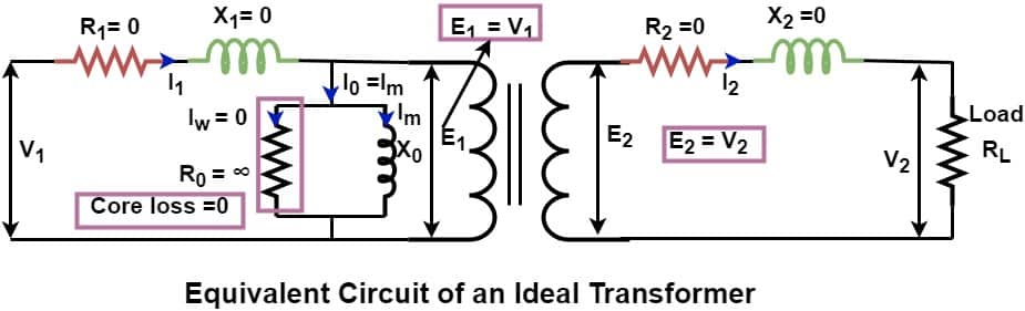
An ideal transformer has the following quantity values.
- Primary resistance – R1=0
- Primary reactance – X1 =0
- Magnetizing reactance – X0 Pure inductive
- Core loss component -R0 =∞ [ Core loss- Iw2R0 = 0 , because Iw =0 ]
- Secondary resistance – R2=0
- Secondary reactance – X2 =0
Working principle of Ideal Transformer
We can redraw the equivalent circuit diagram of an ideal transformer, taking all the transformer quantities mentioned above.
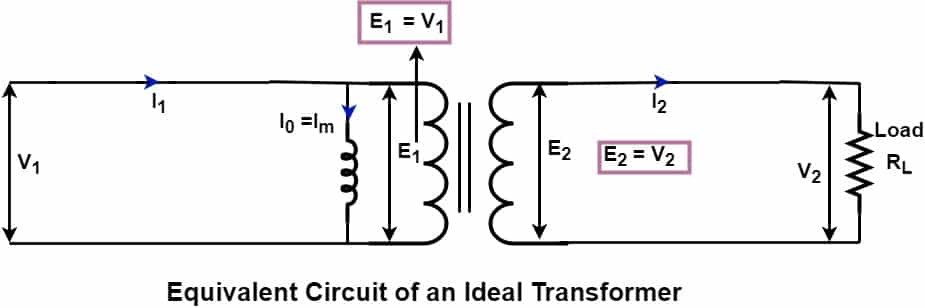
When we feed AC supply V1 to the transformer’s primary, the primary winding induces back EMF E1. In an ideal transformer, the magnitude of E1 is equal to the applied voltage V1 because the transformer has zero winding resistance and leakage reactance. The alternating voltage causes alternating current to flow in the primary. The rate of change of current causes magnetic flux production. The magnetic flux flows in the core and links to the secondary. The voltage induced in the primary and secondary winding depends on;
- Number of turns in the primary and secondary
- Frequency of the supply voltage
- Rate of change of flux
The voltage induced in the primary winding is;
E1 =4.44 N1 f Фm ————–(1)
The voltage induced in the primary winding is;
E2 =4.44 N2 f Фm ————-(2)
E2 /E1 = N2/N1 —————–(3)
Where,
E1 = Induced EMF in the primary winding
E2 = Induced EMF in the secondary winding
N1 = Number of turns in the primary winding
N2 = Number of turns in the secondary winding
f = Frequency
Фm = Flux in the core
Ideal Transformer Equations
The losses in an ideal transformer are zero. Therefore, the input power is equal to the output power.
Input Power = Output Power
P1 = P2
E1 I1 Cos Ф = E2 I2 Cos Ф
E1 I1 = E2 I2
E2 /E1 = I1 / I2 ———–(4)
From equation(3) & (4)
E2 /E1 = I1 / I2 = N2/N1 ——-(5)
Phasor Diagram of Ideal Transformer
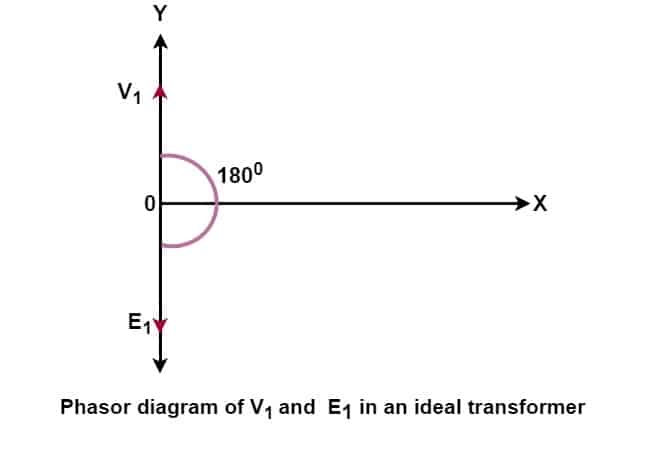
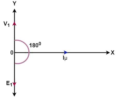
When we apply voltage V1 to the primary, the back EMF (E1) is induced across the primary, which opposes the primary voltage. The magnitude of E1 is equal to V1, and the polarity of E1 is just 180 degrees opposite to V1. The back EMF E1 opposes the applied voltage. The phasor diagram of V1 and E1 is given below.
The transformer draws more current at the instant of switching on of the transformer because the back EMF induced in the primary is zero.
The transformer draws a magnetizing current to set up a magnetic field in the transformer core. The magnetizing current lags the applied voltage by 90 degrees. This current is called the magnetizing current Iμ. The phasor diagram of V1 and Iμ is shown below.
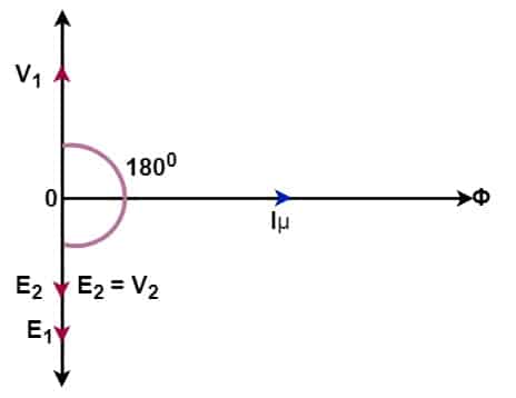
The alternating magnetizing current sets up the alternating flux in the core, and the flux produced is proportional to the magnitude of the magnetizing current, and it is in the phase with the current. The flux produced in the primary gets linked to the secondary and induces E2 voltage. The induced voltage E2 in the secondary is equal to the output voltage V2 of the secondary. The phasor diagram of V1, E1, E2, and Iμ is shown below.
2 thoughts on “Ideal Transformer-Properties, Phasor Diagram, Working”