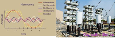
The adverse Effects of Harmonics on Capacitors comprise series and parallel resonance, heating, overloading, and increased dielectric loss. The harmonics also cause a severe problem of resonance that can cause extensive damage. In this post, we will discuss the adverse effect of harmonics on capacitors. Also, we will discuss the series and resonance phenomenon associated with capacitor operation in harmonic-rich networks.
Capacitors are widely used in the electrical network for power factor correction. Electrical loads like induction motors and electric furnaces draw reactive power for their functioning. The reactive current does not contribute to useful work, increasing the line losses in the electrical network. The capacitor banks are installed to compensate for the reactive power. The net current, thus, gets reduced as the capacitive kVAr of the capacitor banks nullify the reactive kVAr,
The capacitors, along with the inductive power system elements, affect system impedance in two ways.
The variable frequency drives, slip power recovery systems, soft starters, and DC drives draw non-linear currents from the supply source, generating harmonics. The working of the capacitor banks under a harmonic-rich environment may be adversely affected.
The resonance between the inductance of the transformer and the capacitance of the capacitor banks may happen at specific harmonic frequencies. The capacitor does not generate harmonics. However, the capacitor can magnify the harmonic current under resonance conditions.
Effect of harmonics on Capacitors: Series & Parallel Resonance
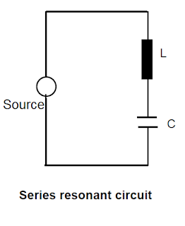
A. Series Resonance
A combination of reactive and capacitive reactance forms a series of resonant circuits.
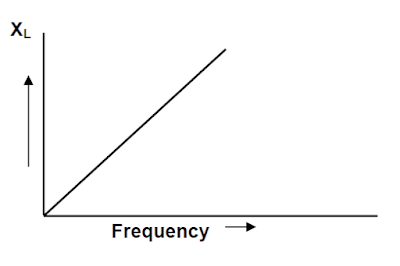
The reactance of the inductor is proportional to the frequency, and reactance increases with an increase in the frequency.
The capacitor’s reactance is inversely proportional to the frequency, and reactance decreases with increased frequency.
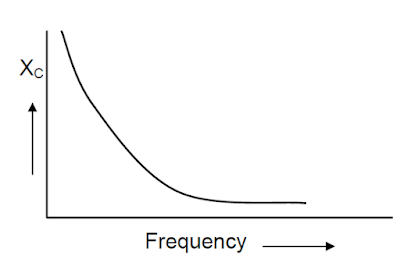
When the inductor and capacitor are connected in the series, the total impedance of the circuit with frequency is as per below the graph.
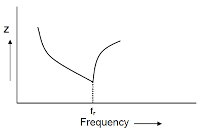
From the above graph, it is clear that at resonant frequency, the impedance of the circuit reduces to a minimum value. The current abnormally increases because of low impedance at the resonant frequency.The reactance of the primary winding of the transformer and the capacitor connected to the secondary winding acts as a series resonating circuit and provides a low impedance path for harmonic currents whose frequency is close to the resonating frequency.
Thus, the circuit offers very low impedance at resonating frequency, which results in a multiple-fold increase in the current.
B. Parallel Resonance
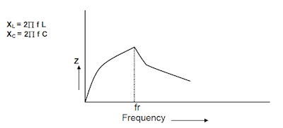
A parallel resonant circuit is formed by the combination of reactive and capacitive reactance connected in parallel.
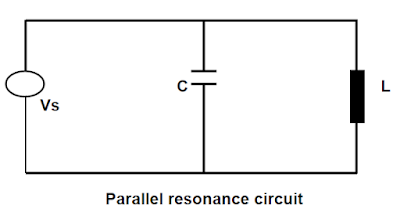
The LV side of the transformer, along with the power factor correction capacitor, behaves as a parallel resonating circuit at a resonating frequency. The impedance offered is very high. Consequently, the harmonic current causes an increased harmonic drop, which may be accompanied by distortion of the fundamental. Transformers and capacitors are additionally loaded.
Under the resonant condition, the capacitor draws excessive current and magnifies the harmonic current. The blowing of fuses and or failure of capacitor banks is the symptom of the harmonic resonant phenomenon. The capacitor draws excessive current and raises the system voltage under resonance. The de-tuned filters are the solution for avoiding resonance in the electrical network.
| Read More : Harmonic Filter Selection |
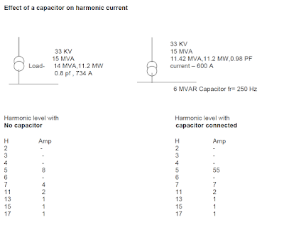
The harmonic current gets amplified under the resonance phenomenon. An illustrative example is given below.
Effect of Harmonics on Capacitors – Illustrative Example
How to Calculate Resonance point in an electrical network?
Point of Resonance :
Computer modeling techniques are used to establish the frequency of resonance of the system along with the capacitor bank. However, for rough calculation, the following formula can be used.
FR = 50 √ ( KVASC / KVARC )
Where,
fR = Resonating frequency
KVAsc = System short circuit level at the point of correction
KVARC = KVAR rating of capacitor bank
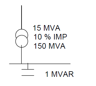
Short circuit MVA
= 15/0.1
MVAsc= 150 MVA
Resonating frequency
FR = 50 √ ( KVASC / KVARC )
= 50 √ ( 150000 /1000 )
FR = 612 Hz
| Read More : Impact Of Harmonics On Induction Motor |
1 thought on “Effects of Harmonics on Capacitors | Interaction of Harmonics with Capacitors”