A parallel resonance circuit has three components, R.L and C, connected in the parallel connection, and the reactance of the inductor cancels the reactance of the capacitor; thus, a parallel resonance circuit behaves as a resistive circuit.
In any alternating current electric circuit, resonance is defined as a condition when the supply frequency does not create any phase difference between the voltage and current, and the circuit acts as a purely resistive circuit even in the presence of reactive elements in the circuit.
This article describes parallel RLC resonance circuits, their resonance condition, various electrical quantities, etc.
What is a Parallel Resonance Circuit?
A parallel RLC circuit in which the supply current remains in phase with the supply voltage is called a parallel resonance circuit. The circuit is depicted in the following figure.
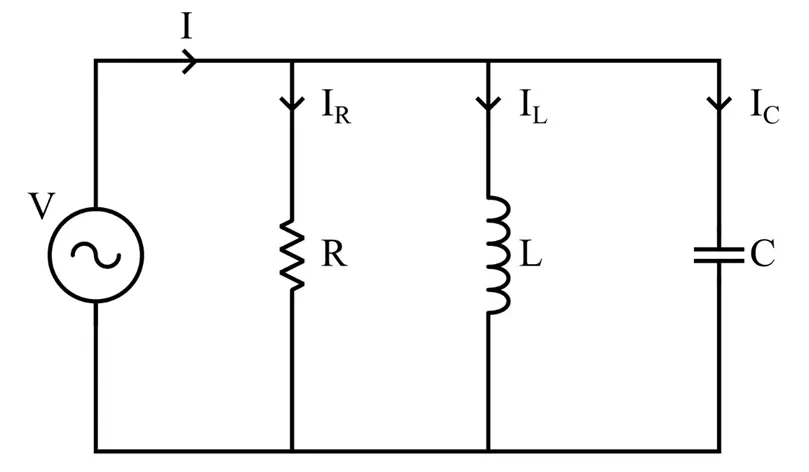
In this circuit, a resistor R, an inductor L, and a capacitor C are connected in parallel across an AC source V.
This circuit will be said to have parallel resonance when the phase difference between the supply voltage and current is zero. At resonance conditions, the inductor and capacitor draw out-of-phase current from the supply source, and thus, the net reactive current is zero, and only resistive current flows in the circuit; and the energy circulation will be between the two reactive elements.
In other words, the parallel resonance in the RLC parallel circuit occurs when the energy stored in the inductor and capacitor oscillates back and forth between them, and no energy will be drawn from the source.
The resonance occurs when the instantaneous values of currents IL and IC are equal and opposite to each other.
Analysis of Parallel Resonance Circuit
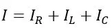
Applying KCL to this parallel RLC circuit, we get,
Also, according to Ohm’s law, we have,
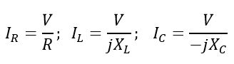
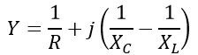
Therefore, the total circuit current is given by,
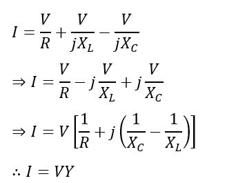
Where,
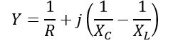
It is called the admittance of the above-given parallel RLC circuit. Now, let us determine different electrical quantities at parallel resonance.
Condition of Parallel Resonance
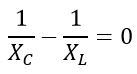
The resonance occurs when the net reactance of the reactive components becomes zero, i.e.,
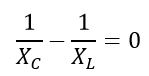
Or,
Electrical Quantities at Parallel Resonance
Now, let us derive the expressions of various electrical quantities in a parallel resonance condition.
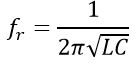
(1). Frequency at Resonance Condition
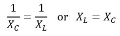
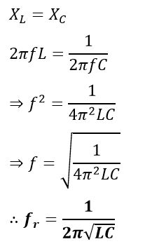
The resonance frequency of a parallel resonance circuit is the value of the supply frequency at which the inductive reactance XL becomes equal to the capacitive reactance XC, i.e.,
Since the XL and XC are given by,
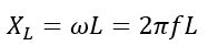
And,
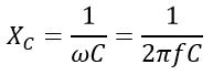
Where ω is the angular frequency, and f is the linear frequency.
At parallel resonance, we have
Also,
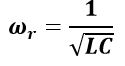
Thus, the resonant frequency of a parallel RLC circuit depends on the value of capacitance and inductance.
(2). Impedance at Resonance
The impedance of the circuit is maximum at resonance, and the circuit draws minimum current.
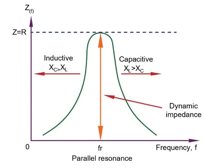
At resonance, the circuit’s admittance has a minimum value and impedes the flow of electric current. Unlike the series resonance circuit, the resistors in a resonant condition have the damping effect; thus, the circuit is less selective.

(3). Admittance at Resonance
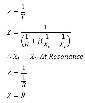
The admittance of a parallel RLC circuit is given by (derived in the above section)
At resonance, substituting XL = XC, we get,
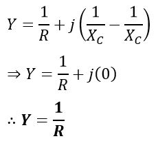
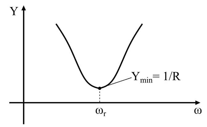
Hence, the admittance of a parallel resonant circuit is equal to the reciprocal of resistance R of the circuit.
(4). Voltage Across Each Element
At parallel resonance,
Therefore,
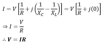
Hence, at parallel resonance, the voltage across each element will be equal to the voltage across the resistance. This is the maximum value of the voltage that appears across each element, as the parallel resonant circuit’s admittance is minimal.
(5). Circuit Current at Parallel Resonance
The circuit current I at parallel resonant condition is given by,
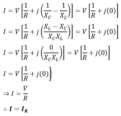
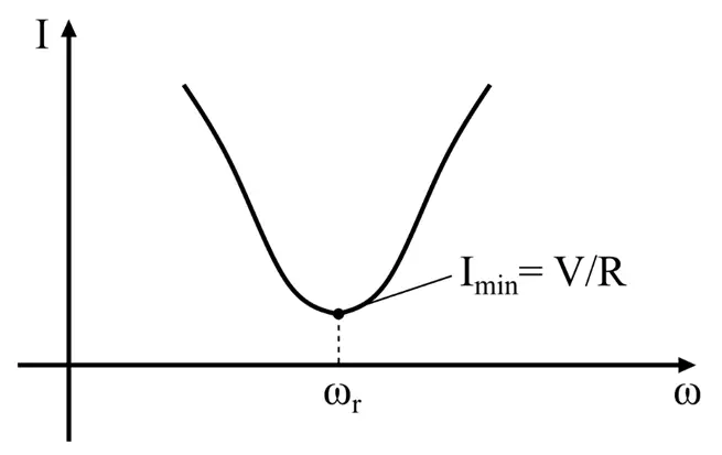
Hence, the current has a minimum magnitude at parallel resonance due to minimum admittance.
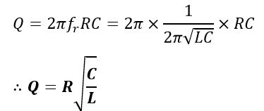
(6). Quality Factor of Parallel Resonance Circuit
The Q-factor or quality factor of a parallel resonance circuit is defined as a ratio of circulating currents to the total supply current, i.e.,
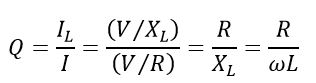
Or
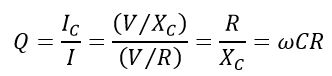
Therefore, the quality factor is,
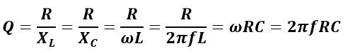
Also, at parallel resonance,
Now, let us consider a solved example of the concept of parallel resonance.
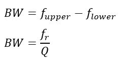
(7.) Bandwidth of a Parallel Resonance Circuit
The difference in upper frequency and lower frequency denotes the bandwidth of the parallel resonance circuit. The upper and lower cut-off frequencies are denoted by ƒupper and ƒlower, respectively. The power dissipation at the upper and lower frequencies is half of the full power dissipated at the resonance frequency fr.
The bandwidth of the parallel resonance circuit is expressed by the following formula.
Solved Problem on Parallel Resonance
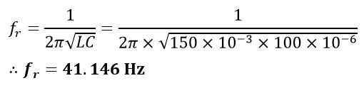
A parallel resonance circuit consisting of a resistance of 100 Ω, an inductance of 150 mH, and a capacitance of 100 µF. This parallel combination is connected across an AC supply voltage of RMS value equal to 120 volts. Compute (i). resonant frequency, (ii). Q-factor, and (iii). circuit current at resonance.
Solution – Given parameter values,
V = 120 Volts, R = 100 Ω, L = 150 mH, and C = 100 µF
(i). Resonant frequency of this circuit:
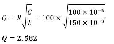
(ii). Quality factor of the circuit:
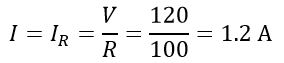
iii). Circuit current at resonance:
Hence, this is all about a parallel resonance circuit, its definition, analysis, and its electrical quantities.