The Quality factor or Q-Factor of a resonant circuit can be defined as the measurement of “quality” or “betterness” of a resonant circuit as far as its performance is concerned. The higher the value of the Quality factor, the narrower the bandwidth provided by the resonant or the tuned circuit. This is a desirable feature in most of the applications.
Resonance in an electrical circuit is a phenomenon that happens at a particular frequency known as the resonant frequency. In an AC circuit consisting of inductors and capacitors, there is a particular value of frequency at which the inductive reactance and the capacitive reactance cancel out each other. This frequency is known as the resonant frequency, and hence, the circuit is said to be in resonance. Under such a situation, all the impedances or the admittances cancel out each other, and the circuit behaves like a resistive circuit with voltage and current being in the same phase.
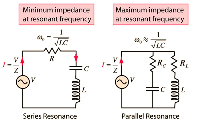
For example, in the case of the series RLC circuit, the frequency at which the resonance happens can be found by equating the inductive and the capacitive impedances(as both of them cancel out each other). So,
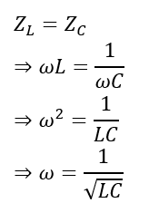
Since,
The frequency at which resonance happens within the series RLC circuit is;
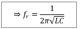
This is, therefore, the resonant frequency. Similarly, we can find out the resonance frequency in the case of the parallel RLC circuit or any other circuit for that matter.
The Birth and Concept of Q Factor
The concept of the Q-Factor or the Quality factor was first given by an engineer named K.S. Johnson from Western Electric Company in the US while he was evaluating the performance of different coils. He devised the concept to make the quality check of the coils a measurable quantity mathematically.
We know that a coil is known for storing energy when some current passes through it. An ideal coil or a pure inductor would, therefore, cause the current to lag by 90 degrees from the voltage across it. However, in reality, there is no pure inductor, and there is a certain amount of inherent resistance that is available within the coil.
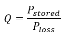
When the current passes through the coil, it causes a certain amount of power loss in the form of heat across the resistance of the coil while a part of the supplied electrical energy gets stored in the coil. Thus, the Quality Factor is formally defined as the ratio between the power stored in the coil or the reactance to the power lost as heat across the coil resistance.
Now,
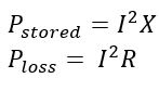
Where I is the current through the coil, and X and R, denote the inductive reactance and the resistance of the coil, respectively.
So, the Quality factor can be given as,
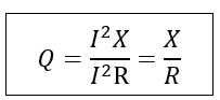
Thus, by knowing the inductive reactance and the Ohmic resistance of a given coil, we can find the Quality Factor. The higher the inductive reactance, the greater the energy stored by the coil compared to the heat loss across the coil resistance, and therefore, the better the quality factor will be.
Quality Factor and Bandwidth
Bandwidth can be defined as the range or extent of frequencies for which the total output power is more than 50% of the maximum power. Bandwidth is the size of the frequency range that is passed or rejected by a resonant or tuned circuit.
One practical application of bandwidth characteristics of a tuned circuit is a radio. By tuning the radio, we select the proper bandwidth and frequency to connect to the proper radio station.
Bandwidth can be calculated by knowing the Quality factor and the resonant frequency of the resonant circuit. Let’s understand this for a series resonant circuit.
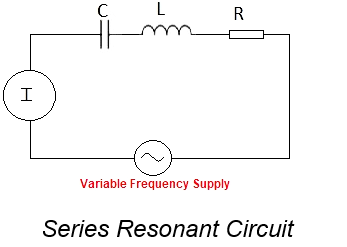
The image above is that of a series resonant circuit supplied through a variable frequency AC supply. The inductive and the capacitive reactance can be written as
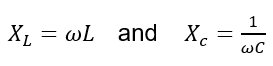
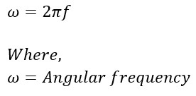
The angular frequency, ω, is directly proportional to the supply frequency (f). Hence, we can say that the inductive reactance is directly proportional to the supply frequency, whereas the capacitive reactance is inversely related to the supply frequency.
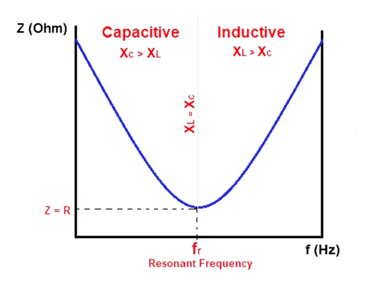
Thus, during the start, when the frequency is low, the capacitive reactance is very high, while the inductive reactance is low. The entire circuit behaves as a capacitive circuit.
The frequency is gradually increased. As a result, the capacitive reactance begins to fall while the inductive reactance starts increasing. The frequency is increased to a point where both the inductive and the capacitive reactance become equal. The frequency at this point is the one which is called the resonant frequency.
If the frequency increases beyond the resonance point, the inductive reactance becomes more significant than the capacitive reactance. The overall circuit thus behaves like an inductive circuit.
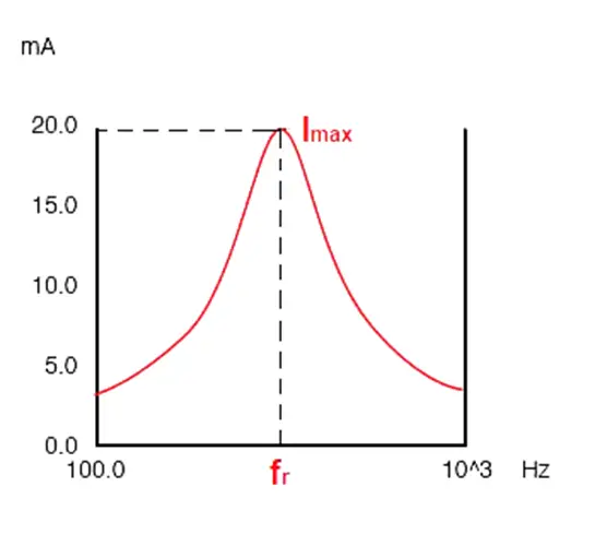
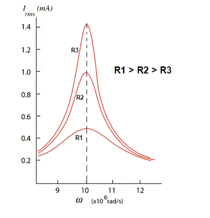
At resonance, the inductive reactance of the above series circuit cancels out the capacitive reactance. Hence, the overall impedance of the circuit reduces at resonant frequency while the current in the circuit rises. This can be shown by the following curves.
Circuit current vs. frequency
Circuit impedance vs. frequency
Now, in the circuit current vs. frequency curve, the peak current can be changed by changing the value of the resistor R. Change in the value of R also changes the Quality factor of the circuit. The lower the value of R, the higher will be the peak current as well as the overall quality factor of the circuit.
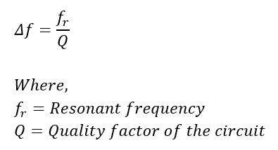
Having discussed the Quality Factor and the Resonant frequency in detail, we can now come to Bandwidth. Mathematically, the bandwidth of the circuit is given as
From the above equation, we can say that with a reduced value of the circuit resistance R, the quality factor increases. As the quality factor increases, the bandwidth of the circuit becomes narrower.
Now, we saw earlier that bandwidth is the range of frequency for which the output power is more than 50% of the maximum power. We get the maximum power at the maximum current. Maximum current is available at the resonant frequency.
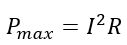
At resonance, the impedance is Z=R, and hence, the power output is given as
To get the bandwidth, we need to know the value of the current for which the power in the circuit reaches 50% of its maximum value. We can calculate this as
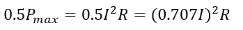
Thus, we get the 50% of the maximum power output at 0.707 or 70.7% of the circuit current. The range between 70.7% of the circuit current on both halves of the resonance point is the Bandwidth(Δf). This can be shown (assuming the maximum current at resonance is 20 mA)
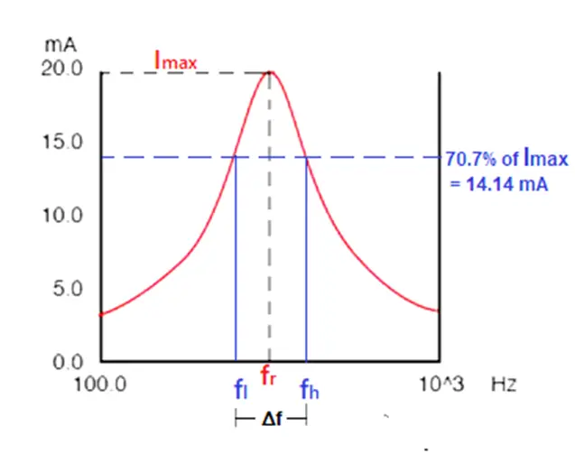
The bandwidth ranges between two cutoff frequencies called the lower band edge (fl) and the upper band edge (fh), as shown in the graph above. Thus,
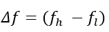
Therefore, we can say that
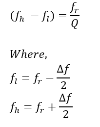
fr is the resonant frequency, also known as the center frequency.
This is how we can calculate and alter the bandwidth as per our requirement by knowing the Quality factor. The quality factor depends upon the circuit resistance. By changing the resistance in the circuit (which is done externally by a potentiometer in an electronic circuit), we can change the Q factor. A change in the Q factor changes the bandwidth. For a high signal-to-noise ratio and clear signal output, high bandwidth is required, which we can get by changing the Q of the circuit.
In the same way, we can analyze any given tuned circuit to get the desired bandwidth by calculating the Quality factor. This is the importance of the Quality Factor or Q factor.