This article describes in detail the voltage in parallel circuits. In a parallel circuit or parallel connection, the electrical devices are connected in parallel.
In a parallel circuit, the voltage is equal across each parallel component. This is because the electrical components are connected at the two sets of electrically common points in a parallel circuit. The potential at the common points of connection is the same and in other words, we can say that the potential across each component is the same in the parallel connection.
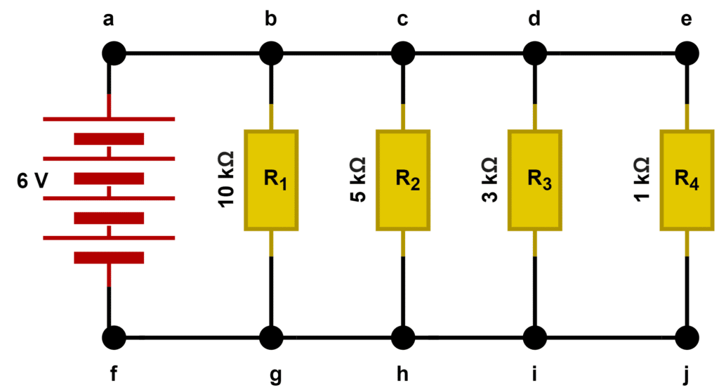
From the above diagram, it is clear that nodes 1, 2, 3, and 4 are the same electrical nodes. similarly, nodes 5, 6, 7, and 8 are the same electrical node. Therefore, the voltage across all the resistances R1, R2, R3, R4, and R5 are equal, which is equal to the voltage across the battery (6 V).
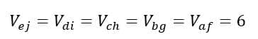
The below circuit shows the closed circuit with a voltage source and a single resistor. The current flowing through the resistor is equal to the total circuit current and the voltage across the resistor is equal to the source voltage.
The current in the circuit is;

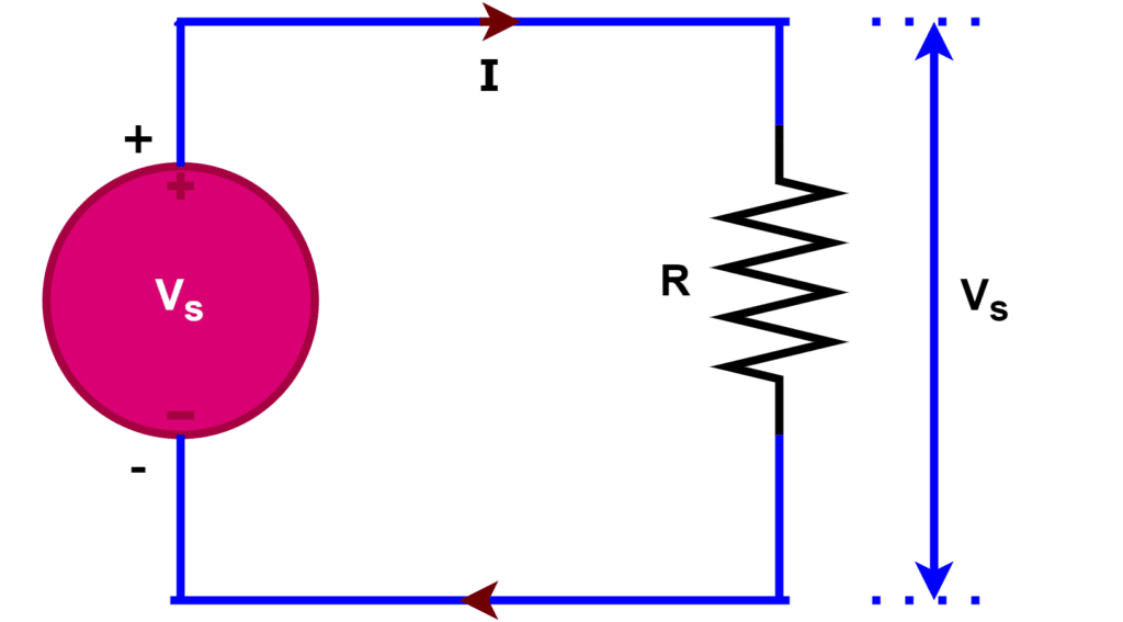
The below circuit is a closed circuit having three resistors(R1, R2 & R3) connected in parallel with a voltage source(Vs).
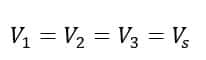
In the above circuit, one end of each resistor is connected to one end of the battery terminal and the other end of each resistor is connected to the other end of the battery. Thus, we can say that the voltage across each resistance is equal to the source voltage. Mathematically we can express the voltage across resistors as;
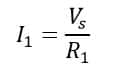
The current through the R1 resistor
The current through the R2 resistor

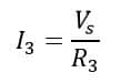
The current through the R3 resistor
The total current in the above parallel circuit is;
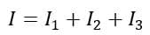
From the above expression, it is clear that the total current in the circuit increases when we add additional branches in a particular parallel circuit.
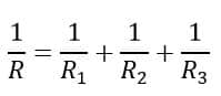
The equivalent or effective resistance(R) of the above parallel circuit can be calculated by following mathematical expressions.
Advantages of Parallel Circuits
To understand the advantages of parallel circuits, let us take an example. Let three bulbs of voltage rating(V) be connected in the series, and finally connected to a voltage source(V). The circuit diagram of the arrangement is shown in the below figure.
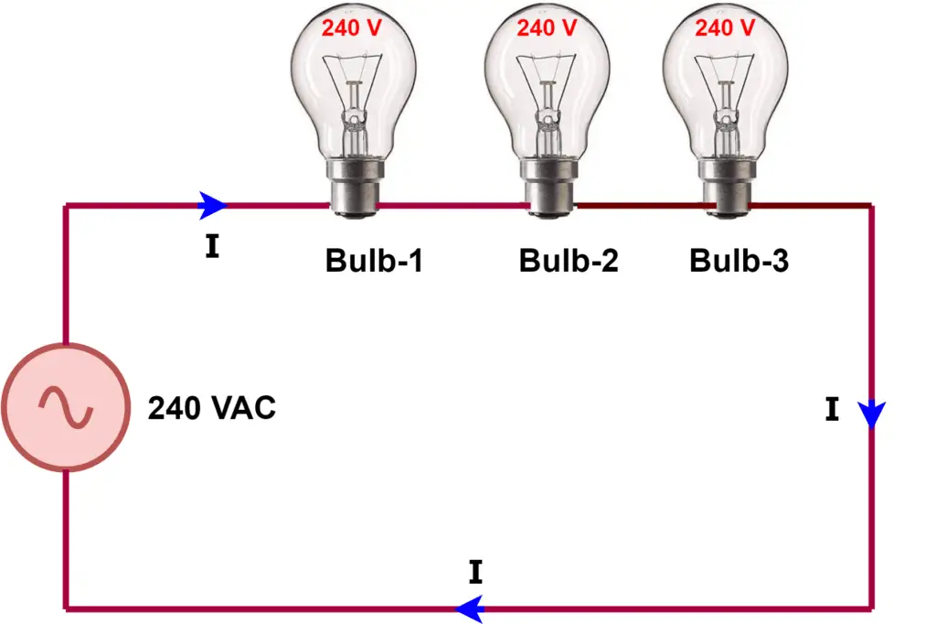
When we connect three bulbs to a single voltage source in the series connection, the following problems occur.
- It is not possible to turn on and turn off individual bulbs.
- All bulbs do not glow with full-rated intensity.
- The circuit becomes an open circuit if there is a problem with any of the bulbs.
The connection diagram of three bulbs connected in parallel is given below.
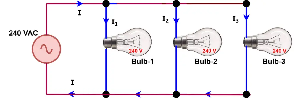
All three bulbs connected in parallel get the full supply voltage and the results are the followings.
- All the bulbs glow at their rated intensity.
- The bulbs get the rated voltage.
- It is possible to operate the bulbs individually.
- In the case of a defect in any of the bulbs, the other healthy bulbs keep operating. The faulty bulbs can be replaced.
Parallel Circuits in Home
All our home electrical appliances are connected in parallel with each other. Therefore, we can operate individual appliances separately without affecting others. For example. we can turn on the washing machine without turning on or off the mixer or any other electrical appliances.
The electrical circuit has phase, neutral, and earth conductors. In healthy electrical condition, the current flow between phase and neutral when we switch on any electrical appliance. The earth conductor protects the electrical system in a faulty condition. When the live phase touches to earth, a large amount of electric current flow through the phase wire and the fuse in the series of the live phase gets blown off under earth fault condition.
When we plug the electrical connector into the socket the appliance receives a power supply. Thus, on switching appliances, it gets full voltage for its operation.
Application of Voltage in Parallel
The applications of voltages in parallel comprise the followings:
- Household electrical appliances
- Lighting circuits
- Power ring
- Capacitors for power factor improvement.