An infrared flue gas analyzer measures the amount of traces of gases by determining the absorption of an emitted infrared light source through a certain air sample. An infrared flue gas analyzer enables the measurement of the number of many gases in a complex gas mixture to be measured in an industrial environment.
An infrared flue gas analyzer works on the very basic principle of absorption of the gas. A portion of the infrared spectrum gets absorbed when the infrared beam passes through some gases like carbon dioxide and carbon monoxide. Some diatomic elemental gases such as oxygen, hydrogen, nitrogen, etc. do not exhibit such characteristics.
The amount of particular frequency of light that gets absorbed by the gas, (when the light is passed through it) determines the amount of gas present. The concentration of any of the components present in the gas that exhibits the infrared absorption characteristics in a mixture can be determined by its unique absorption pattern.
Construction of an Infrared flue gas analyzer
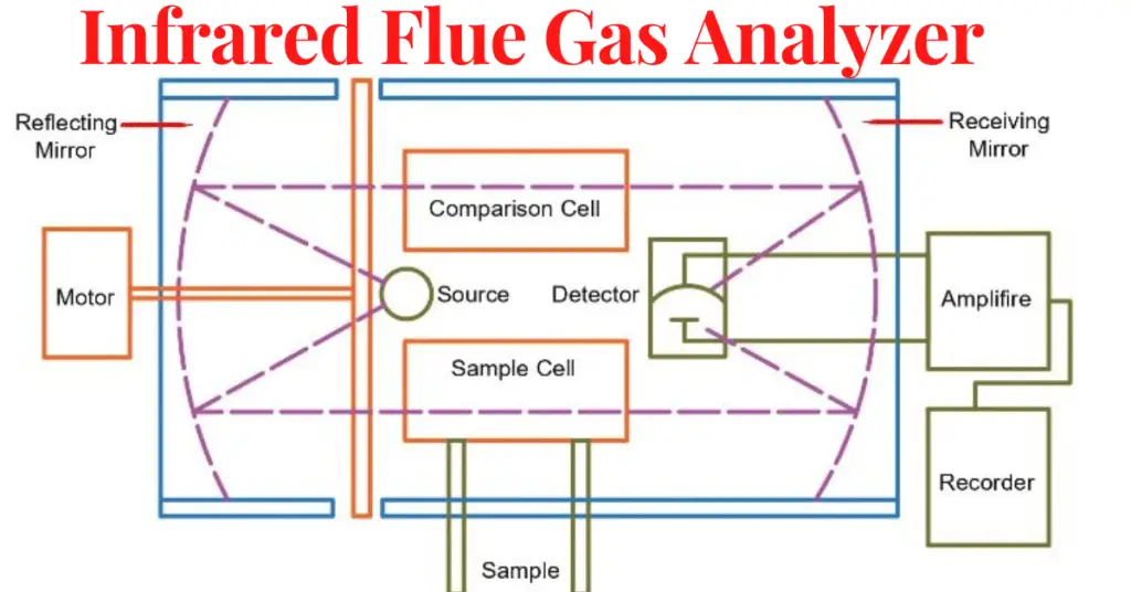
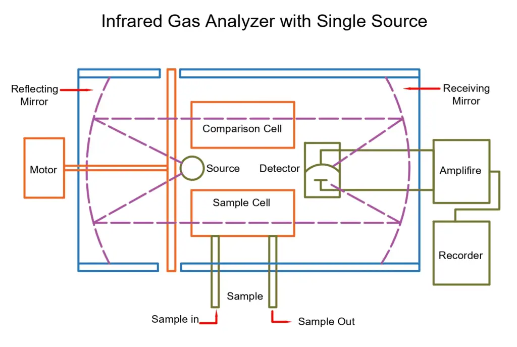
The below figure shows an infrared flue gas analyzer that uses infrared techniques for measuring the gases.
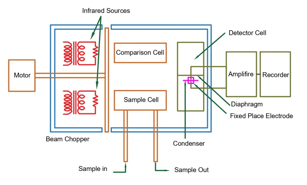
As seen in the figure, an infrared flue gas analyzer consists of a motor, infrared source, beam chopper, detector cell, condenser, amplifier, and recorder.
Infrared Radiation Sources:- For the two infrared sources, Nichrome filaments may be used as an infrared radiation source. The light beams from the sources are made to travel through the sample cell and the comparison cell respectively.
Beam Chopper:- The beam chopper is a mechanism in the analyzer which is placed between the source and the cells. The beam chopper operates in such a way that it alternatively interrupts the light radiation to the sample cell and the comparison cell. The emergent radiation from both the sample cell and the comparison cell enters at the opposite ends of the detector cell.
Detector Cell:- This detector cell is divided into two main compartments by a metallic diaphragm. The detector cell is filled with the gas to be measured at the same pressure. The condenser connected to the amplifier does the further processing.
Condenser:- The condenser is formed by combining a metallic diaphragm and a fixed electrode. The different light frequencies are absorbed by the different molecules that are present in the air. The absorbed frequency that is measured clearly relates to the amount of the particular gas present in the air. For every optical analyzer and for every absorption type, the absorption spectrum of infrared radiation is unique for various gases.
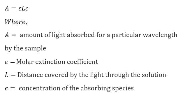
Beer Lambert’s law gives the fundamental equation relating photon absorption to substance concentration.
Beer Lambert’s Law
The Beer-Lambert law states that there exists a linear relationship between the concentration and the absorbance of the solution, which enables the concentration of a solution to be calculated by measuring its absorbance.
Infrared Flue Gas Analyzer Working Principle
The comparison cell is filled with a diatomic gas, for example, O2, N2, or H2 gas. The gas filled in the comparison cell must not absorb the infrared energy. The sample cell is also filled with the same gas as that in the comparison cell to adjust the zero of the analyzer. After the zero is set, the sample gas is made to pass through the sample cell.
The amount of infrared energy absorbed and the rate of absorption of the infrared energy depends upon the components present in the sample gas. Here, for example, we measure Carbon Dioxide (CO2) components. The detector cell should be filled with Carbon Dioxide (CO2) gas on both sides.
When it is under operation, the energy received from the sample side in the detector will be less by an amount that is equivalent to the Carbon Dioxide (CO2) component present in the sample as compared to the energy received from the comparison cell. The difference in the energy levels received and absorbed by the Carbon Dioxide (CO2) present on both sides of the detector cell would cause a temperature difference. This temperature difference causes a pressure difference.
The chopper allows entry only alternative to the beam. So, the metal diaphragm will vibrate at the chopping frequency and will have the magnitude of the displacement from the fixed electrode equivalent to the Carbon Dioxide (CO2) content sample. The chopping frequency usually varies from 2 Hz to 10 Hz. The measure of the Carbon Dioxide (CO2) value will determine the capacitance of the condenser.
The condenser capacitance is measured using an amplifier and calibrated for indicating and recording purposes. If the same analyzer is to be used for measuring the Carbon Monoxide (CO), the detector cell should be filled with the Carbon Monoxide (CO) and the calibration should be done accordingly.