Capacitors in series draw the same current and store the same amount of electrical charge irrespective of the capacitance value.
In this article, we will learn the series connection of capacitors and will also derive the expressions of their equivalent capacitance. The capacitors in series technically behave as the resistors and inductors in parallel. So, the analysis of the capacitors in series connection is quite interesting and plays a crucial role in electronic circuits.
Capacitors in Series Connection
When multiple capacitors are connected, they share the same current or electric charge, but the different voltage is known as series connected capacitors or simply capacitors in series.
The following figure shows a typical series connection of four capacitors.
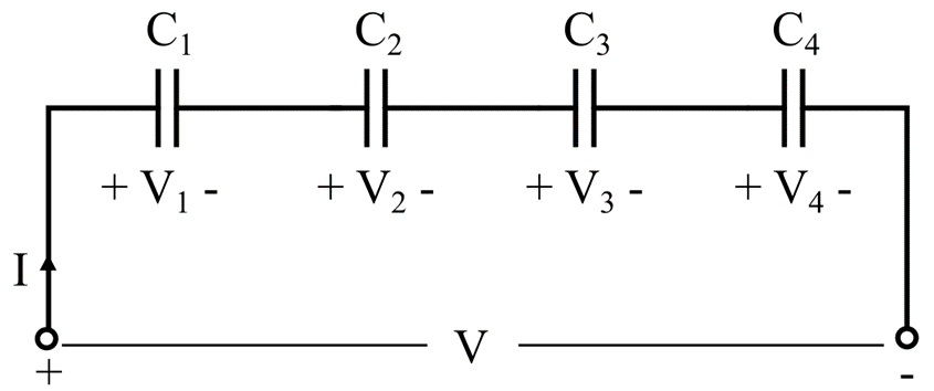
In this type of connection, the left-hand plate of the first capacitor, C1, is connected to the positive terminal of the supply source, and its right-hand plate is connected to the left-hand plate of the capacitor, the right-hand of capacitor C2 is connected to the left-hand plate of capacitor C3, and a right-hand plate of capacitor C3 is connected to left-hand plate of capacitor C4, and finally the right-hand plate of capacitor C4 is connected to the negative terminal of the supply source.
From the circuit diagram, we can point out that
- The same current and electric charge flows through all the capacitors.
- There is a different voltage across each capacitor, which depends on the capacitance value of the capacitor.
- The total voltage across the combination of capacitors equals the voltages across individual capacitors.
Capacitance of Capacitors Connected in Series
Let us now analyze the capacitor circuit shown in the figure above to derive the equivalent capacitance expression.
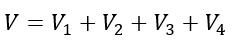
In the above circuit, the total applied voltage can be given by using KVL, i.e.
Since the voltage across a capacitor is given by,

Q is the capacitor’s charge, and C is the capacitance of the capacitor.
Therefore, the total voltage is given by,
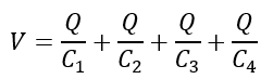
From the above expression, the charge on each capacitor is the same since the current through each capacitor remains the same.
Rearranging the equation, we get,
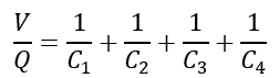
Since,

Therefore, the equivalent capacitance of the capacitors will be,
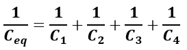
When n numbers of capacitors are connected in series, then their equivalent capacitance is given by,
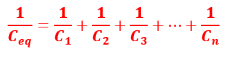
From these two expressions, it is clear that the mathematical expression of equivalent capacitance of capacitors in series is in the same form as the expression of resistance in parallel.
The total capacitance ( CT ) of the series connected capacitors is always less than the value of the smallest capacitor in the series connection. If two capacitors of 10 µF and 5 µF are connected in the series, then the value of total capacitance will be less than 5 µF.
Capacitance of Two Capacitors in Series
The connection circuit is shown in the following figure.
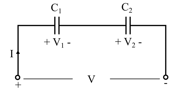
To get an idea about the equivalent capacitance, Let us now derive the expression of the equivalent capacitance of two capacitors.
As per the above equation of equivalent capacitance, we have,
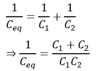
Therefore,
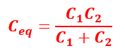
Hence, when two capacitors are connected in series, their equivalent capacitance can be directly calculated by multiplying the two capacitances and then dividing by their sum.
Let’s consider another special case, when two capacitors have the same capacitance, i.e., C1 = C2 = C.
In this case, we get,
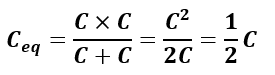
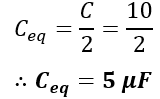
Therefore, when n capacitors of the same capacitance are connected in series, then their equivalent capacitance is given by,

Now, let us consider an example to understand how to use these formulae in calculations.
Voltage across Capacitors
The capacitive reactance of the capacitor is frequency dependent, and it opposes the flow of electric current and creates impedance in the circuit. The reactance of each capacitor causes a voltage drop; thus, the series-connected capacitors act as a capacitive voltage divider.
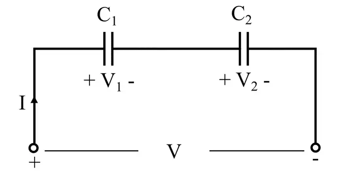
The voltage drop across capacitors C1 and C2 in the above circuit is V1 and V2, respectively. Let the equivalent capacitance of the capacitors be Ceq.
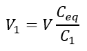
The voltage drop across capacitor C1 is;
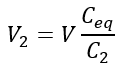
The voltage drop across capacitor C2 is;
Now, let us consider an example to understand how to use these formulae in calculations.
Solved Problem
Numerical Example – Find the equivalent capacitance of series combination for the following cases:
(1). When three capacitors C1 = 10 µF, C2 = 15 µF, and C3 = 12 µF are connected in series.
(2). When two capacitors C1 = 10 µF and C12 = 20 µF are connected in series.
(3). When two capacitors C1 = C2 = 10 µF are connected in series.
Solution –
Case (1): When three capacitors are connected in series:
C1 = 10 µF
C2 = 15 µF
C3 = 12 µF
Using the formula of equivalent capacitance, we get,
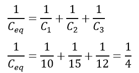
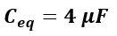
Therefore,
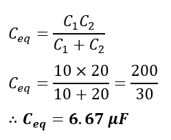
Case (2): Equivalent capacitance of two capacitors
C1 = 10 µF
C2 = 20 µF
The equivalent capacitance will be,
Case (3): When two capacitors have the same capacitance value
C1 = C2 = 10 µF
Hence, this is all about capacitors in series and their formula. In this article, we have studied the capacitance of a series-connected capacitors and numerical examples based on that.
Related Articles: