Electrical power is the most widely used form of energy because it can be transmitted and distributed far more easily than other forms, such as mechanical energy. Electrical power distribution system includes various components and processes that ensure a reliable and efficient supply of electrical power at appropriate voltage levels.
Now, let’s look at how consumers use electrical power.
What is a Electrical Power Distribution System?
An Electrical Power Distribution System is a network designed to deliver electricity from the transmission system to individual consumers, such as homes, businesses, and industries. It involves a series of components and processes that ensure an efficient and reliable electrical power supply at the appropriate voltage levels.
Electricity is the lifeline of any economy in the world, and the demand for electrical power is rising exponentially. Power generation companies do their best to meet these demands efficiently and without disruption. Electrical power is generated at war footing using every possible resource – from fossil fuels to solar, wind, and nuclear.
However, generating huge amount of power and meeting the end-user demand are two different things. This is because merely having an efficient power generation mechanism in place is not enough but it should be backed by an efficient transmission (high voltage, low current) as well as distribution system (step-down voltage for safety).
Let’s understand how the generated power is distributed efficiently and reliably among consumers.
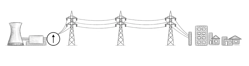
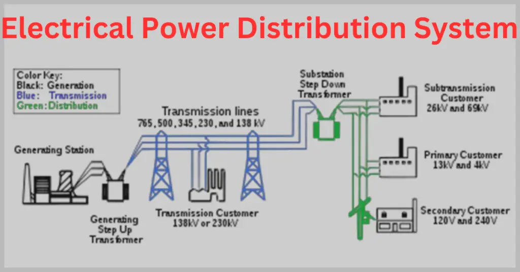
Electric Power Distribution Diagram
The electric power distribution diagram is shown below.
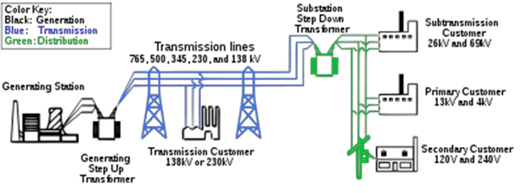
Power plants are located in remote areas from where it has to be transmitted to a distribution station in the city or village. This distribution station then dispatches the power to the consumers. Hence, without an efficient system of transmission and distribution, a huge proportion of the generated power will be lost (primarily due to I2R copper losses in the conductors).
Moreover, this power is transmitted and distributed through open areas or public spaces. Hence, an efficient and safe system is important.
Functions of Distribution Systems
1. Power Delivery
The primary role of a distribution system is to carry electricity from generation points to consumers. This is achieved through a well-connected network of substations, transformers, and distribution lines that ensure efficient and reliable energy transfer to homes, industries, and businesses.
2. Voltage Regulation
Maintaining stable voltage levels is essential for the safe operation of electrical equipment. Distribution systems use devices like voltage regulators and transformers to control fluctuations and keep voltage within permissible limits across the network.
3. Fault Management
Distribution systems are designed to quickly detect and handle faults such as short circuits or equipment breakdowns. Protective devices like circuit breakers and fuses are strategically installed to isolate the affected section, minimizing disruption and preventing widespread power outages.
4. Load Balancing
Distribution systems are structured to evenly distribute electrical demand across multiple feeders and substations. This prevents excessive stress on transformers and supply points, helping to maintain system efficiency, reduce losses, and ensure consistent and reliable
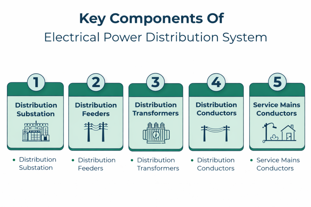
Key Components of Electrical Power Distribution System
Power is generated and transmitted at a higher voltage using a power transformer. This is done to reduce the reliance on higher currents for the transmission of this huge amount of power and to improve the power factor. However, at the distribution end, this voltage is again reduced before being distributed among the consumers. There are various parts of a power distribution system.
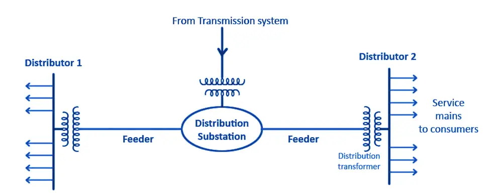
- Distribution Substation
- Distribution Feeders
- Distribution Transformers
- Switchgears
- Distribution Conductors
- Service Mains Conductors
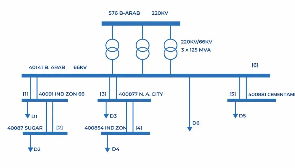
1. Distribution Substation
A distribution substation is the junction which receives the transmitted power. It is located at the outskirts of a city or a village or an industrial area. The transmitted power is at a very high voltage (like 400kV, 800kV etc. depending on the distance) which is stepped down at a distribution substation. The stepping down of the voltage is done at the required levels for Primary distribution which is followed by secondary distribution system.
2. Distribution Feeders
The power lines that transfer the power from substation to the distribution transformers are known as distribution feeders. Feeders have no tapping to keep the current constant. The main consideration in the design of a distribution feeder is its current carrying capacity.
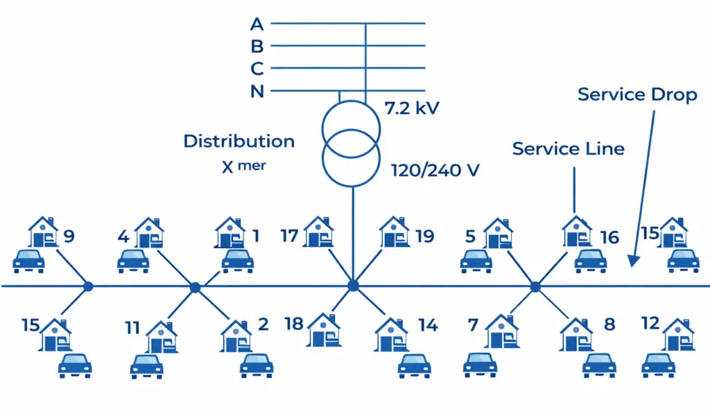
3. Distribution Transformers
A distribution transformer is a three-phase transformer that steps down the voltage from the distribution levels to the one suitable for the primary and secondary consumers. It is also known as a service transformer. These are typically Delta-Star (Δ-Y) connected transformers.
The distribution transformer steps down the voltage to a level where the voltage between a phase and the neutral is 220V and between phase to phase is 415V. However, in the US and some other countries, the phase-to-phase voltage is 240V, while the single-phase voltage is 120V.
Distribution transformers normally have ratings of less than 200kVA. These transformers must work 24 hours to maintain the power supply; hence, they are designed to have lower iron losses(core losses). Usually, they don’t operate at full load; hence, they are designed to have greater efficiency even at smaller loads.
4. Switchgear
Switchgear refers to an assembly of electrical components used to control, protect, and manage the flow of power within a system. It includes devices such as circuit breakers and isolators that enable switching operations and ensure safe regulation of electricity.
5. Distribution Conductors
After the voltage is stepped down by a distribution transformer, the output is taken out by the distribution conductors. These conductors have tappings through which the power is distributed from the distribution end to the consumers. As there are multiple tappings, the current through the distribution conductors is not the same. The voltage drop, however, in the distribution conductors must be as low as possible (as voltage variation is the main design criteria for distributors).
6. Service Mains Conductors
Service mains conductors are the conductors that connect the distribution conductor at the nearest pole to the consumer’s facility.
Classification of Electrical Power Distribution System
The classification of distribution systems is based on the nature of current, construction type, and the scheme of connection used.
1. Based on Current( (Nature of Current)
DC Distribution system
The transmitted AC power can be rectified at the distribution substation using power electronic converters and can be distributed as per the consumer’s requirement. This is highly efficient for specific industrial applications and long-distance high-voltage links. HVDC distribution is of two types,
- Unipolar DC Distribution system (2-wire DC distribution)
- Bipolar DC Distribution system (3-wire DC distribution)
Unipolar DC Distribution system (2-wire DC distribution)
A unipolar DC distribution system, also known as a 2-wire DC system, uses a single conductor to supply electrical power, while the return path is provided either through the ground or an additional conductor. It is commonly used in low-voltage applications such as battery-operated devices and small electronic systems.
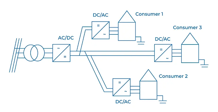
The system is simple in design because it requires minimal wiring, which also makes it cost-effective for specific uses. However, it has limitations in terms of current-carrying capacity and is not suitable for high-power applications. Additionally, relying on the ground as a return path can lead to safety concerns and make proper grounding more difficult.
Bipolar DC Distribution system (3-wire DC distribution)
A bipolar DC distribution system, also known as a 3-wire DC system, uses two main conductors—positive and negative—along with a neutral conductor for power distribution. In this arrangement, the positive and negative lines carry equal and opposite currents, which helps maintain a balanced system. It is commonly used in higher-voltage DC applications, including certain industrial setups and renewable energy systems.
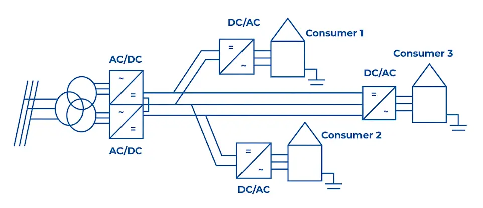
This system offers the advantage of reduced voltage drop over long distances due to the use of multiple conductors. The presence of a neutral wire also improves grounding conditions, enhancing overall safety and system stability. However, compared to unipolar systems, it is more complex because of the additional conductor and design requirements. It also involves higher installation costs due to the need for extra materials and components.
AC Distribution System
It is the most widely used system of power distribution as almost all the loads, whether commercial or residential, run on AC power. Hence, the transmitted power at high voltage is stepped down to a suitable voltage for the end users at the distribution substation and then dispatched. Typically functions at a frequency of 50 Hz or 60 Hz, depending on the region in which the system is used. There are two types of AC distribution system.
- Primary Distribution System
- Secondary Distribution System
Primary Distribution System
The Primary distribution system caters to the power demand of big consumers, such as factories and industries. It operates at a higher voltage than that required for ordinary or residential consumers. The transmitted power is stepped down to the primary distribution voltage, which is usually 11kV but can be between 2.4kV and 33kV, depending on the demand type.
Commonly used primary distribution voltages in most countries are 11 kV, 6.6 kV and 3.3 kV. Primary distributor also feeds a small substation from where the secondary distribution is carried out. Primary distribution is carried out by three phase three wire system to optimize conductor material costs.
Secondary Distribution System
The Secondary distribution system caters to the power demands of residential consumers, small factories, shops, and other commercial setups. Domestic or residential consumers are supplied with single phase power supply at 220~240 Volts or 120 Volts (in the US and some other countries).
Three-phase supply is also provided at 415 Volts to commercial buildings, malls, big properties, small factories, etc. Secondary distribution is carried out by a three-phase, four-wire system, providing a neutral path for unbalanced loads
AC distribution systems can also be categorized based on phase configuration into single-phase and three-phase systems. Common arrangements include single-phase two-wire, single-phase three-wire, two-phase three-wire, two-phase four-wire, three-phase three-wire, and three-phase four-wire systems. Among these, the three-phase, four-wire system is widely used in secondary distribution due to its ability to provide a neutral path and support both single-phase and three-phase loads efficiently.
2. Based on Construction Type (Position)
Overhead Distribution System
This is the traditional and most common method of power distribution. In this method, the power is distributed through overhead wires attached to roadside electric poles and towers. It utilizes bare conductors supported by insulators, making it the most economical choice for rural and suburban areas.
Transformers and other important equipment are mounted on these poles or similar supporting structures. This system is cost-effective and easy to maintain requiring less managerial overhead. However, being exposed to the outer atmosphere, it is subject to various weather phenomena such as lightning strikes and wind damage.
Underground Distribution System
Modern advancements in electrical power distribution has given the popularity to the underground distribution system. This system doesn’t need poles and supporting structures and has no overhead hanging wires.
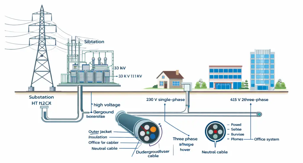
It offers superior safety and aesthetics for urban environments. However it is costlier than its overhead counterpart and tough to maintain due to difficulty in fault localization.
3. Based on Connection Type
Radial Distribution
This electric power distribution system is used where the distribution substation is located at the center of the consumers from where the feeders radiate and distribute the power in all directions. The flow of power in radial distribution is in one direction.

Radial distribution is cost-efficient, but a major drawback is that a fault in a feeder can result in a power outage for all the consumers connected to it.
Parallel Feeder Distribution System
The parallel feeder system was introduced to tackle the disadvantage of the radial distribution system. In this system, instead of a single feeder, parallel feeders are used for power supply. This redundancy ensures that if one feeder fails, the load is automatically transferred to the healthy parallel line. The cost of this system is higher, but it is more reliable than its radial system counterpart.
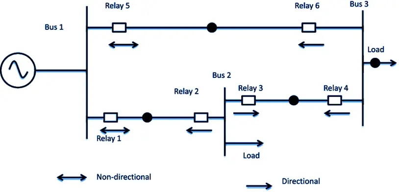
Ring Main Distribution System
A ring main distribution system comprises feeders connected in a closed loop or ring configuration, with distributors tapped from different points along the ring. This system forms a continuous loop network without any terminating end in the feeders.
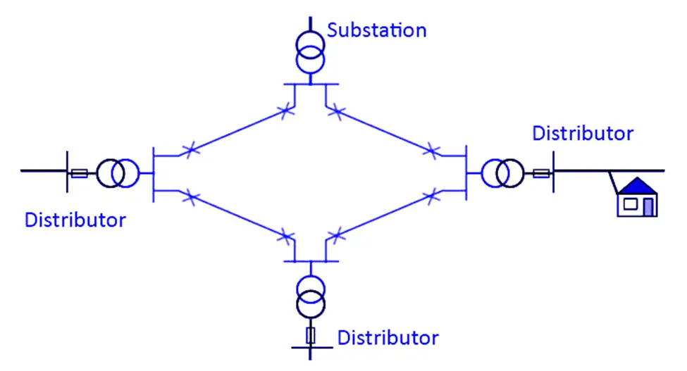
The advantage of this system is its reliability, as each distribution transformer is fed by two feeders. This ensures the continuity of the power through an alternative path in the event of a fault in any section of the feeder, allowing for maintenance without total power loss.
Inter-Connected System
When a ring main feeder is energized by two or more independent substations or power plants, it is known as an interconnected system. This is the most reliable configuration, as it ensures peak load sharing and maintains service even if one substation experiences a total failure.
Summary Table: Power Disribution System Based on Connection Type
| Distribution Type | Configuration | Power Flow | Reliability | Cost | Key Advantage | Main Disadvantage |
| Radial Distribution | Single feeder from substation | One direction | Low | Low | Simple and economical | Fault causes total outage |
| Parallel Feeder System | Multiple feeders supply same load | Multiple paths | Medium to High | High | Backup supply available | Higher installation cost |
| Ring Main System | Closed loop (ring) | Bi-directional | High | Moderate | Alternative supply path | More complex protection |
| Interconnected System | Multiple substations connected | Multiple directions | Very High | Very High | Maximum reliability & load sharing | Highly complex and expensive |
Key Power System Performance Requirements
To be considered an efficient system, a distribution network must satisfy these technical benchmarks:
- Voltage Stability: Voltage fluctuations must be strictly controlled. For example, in India, the statutory limit is ± 6% of the rated voltage at the consumer end.
- Reliability of Service: The design should prioritize continuity of supply, minimizing the impact of localized faults.
- Capacity on Demand: The system must be capable of handling peak load requirements without overheating conductors or tripping protection devices.
Related Articles:
- T model of Transmission Line
- Difference between Power Transformer & Distribution Transformer
- Difference between Transmission Line and Distribution Line
- Microgrids
- Benefits of Smart Grids
- Load Bus, Generator Bus and Slack Bus
- Symmetrical Components in Power Systems
- Electrical Transmission Tower: Types, Design & Parts