In this article, we will discuss the RLC Series AC Circuit and will analyze its behavior in the application of sinusoidally varying ac voltage. So, let’s start with the basic introduction of the RLC series circuit.
What is RLC Series Circuit?
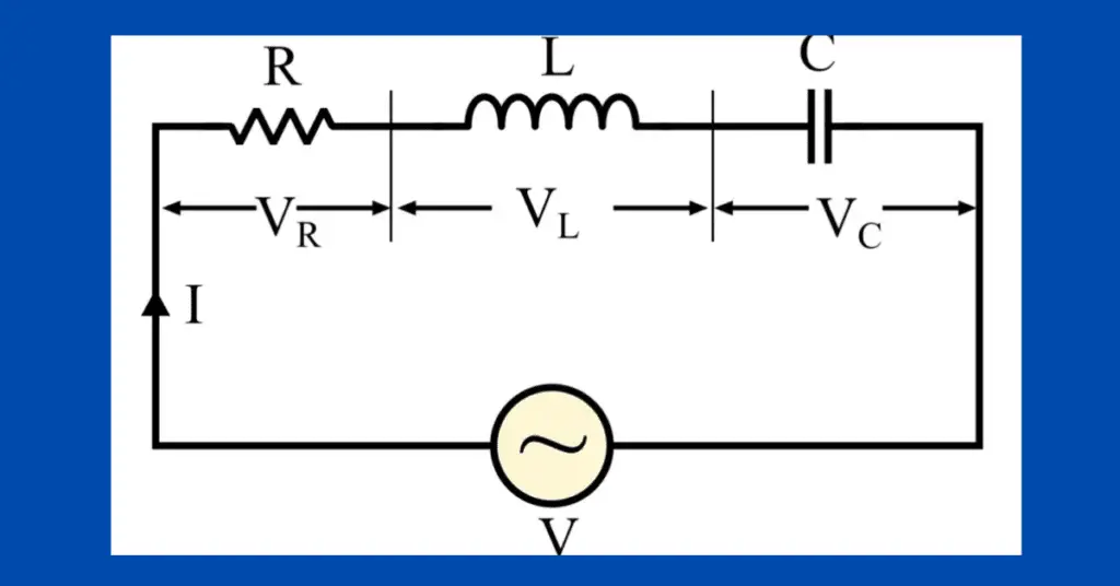
An AC electric circuit in which resistor (R), inductor (L), and capacitor (C) are connected in series combination and this combination is excited by an ac voltage source, then it is called an RLC series circuit.
A typical RLC series circuit consisting of R, L, and C in series across an alternating voltage source (V) is shown in figure-1.
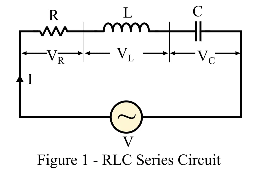
In this circuit, the RMS value of the total circuit current is I. Then the voltage drop across each element is given by,
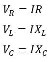
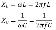
Where XL and XC are the inductive reactance and capacitive reactance respectively.
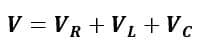
In the RLC series circuit, the total voltage is equal to the phasor sum of the voltage across R, L, and C, i.e.
Phasor Diagram of RLC Series Circuit
We can represent this voltage relation with the help of a phasor diagram which is shown in figure-2.
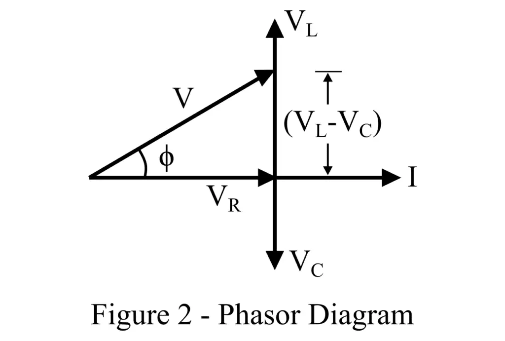
Since the current through all the elements is the same, hence it is taken as the reference phasor. As we know, in a resistor current and voltage remain in the same phase, in an inductor, the current lags the voltage by 90°, and in a capacitor, the current leads the voltage by 90°.
Therefore, in the phasor diagram, the voltage drop across resistor VR is represented in phase with the current, the voltage drop across inductor VL is represented lagging behind the current phasor by angle 90°, and the voltage drop across capacitor VC is represented leading ahead of the current phasor by 90°.
Depending on the magnitude of inductance and capacitance, the circuit can be either effectively inductive or capacitive depending on the magnitude of voltage drop VL or VC.
If VL > VC, then the circuit will be effectively inductive, and the voltage across reactive components (L and C) is then given by (VL – VC). If VL < VC, the circuit will be effective capacitive, and the voltage across reactive components will be (VC – VL).
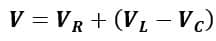
Now, for the case, let us consider (VL – VC) to be the net voltage drop across the combination L and C. Thus, the total applied voltage will be the phasor sum of VR and (VL – VC), i.e.
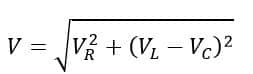
The magnitude of the voltage is given by,
Substituting values of VR, VL, and VC, we get,
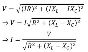
Here, the quantity in the denominator is the total opposition offered by R, L, and C in the path of the current. It is called the impedance of the RLC circuit.
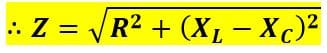
Here, the values of XL and XC are given by,
From the expression of impedance (Z), we can state the behavior of the RLC series circuit as follows:
- When XL > XC, i.e. (XL – XC) is positive – The RLC series circuit will be effectively inductive.
- When XL < XC, i.e. (XL – XC) is negative – The circuit will be effectively capacitive.
- When XL = XC, i.e. (XL – XC) is zero – The RLC series circuit will be effectively resistive.
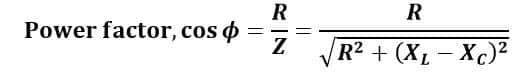
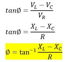
From the phasor diagram, we can also determine the power factor of the circuit as follows,
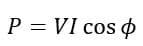
Also, the power consumed by the RLC circuit is given by,
Hence, this is all about the RLC series circuit, its phasor diagram, and analysis. To understand the application of expressions derived in the above section, consider the following solved examples.
Phase Angle of RLC series Circuit
The phase Angle of the RLC series Circuit from the above phasor diagram is;
Impedance Triangle of RLC Series Circuit
The impedance triangle of the RLC series circuit is shown below.
Case-1: when (XL > XC)
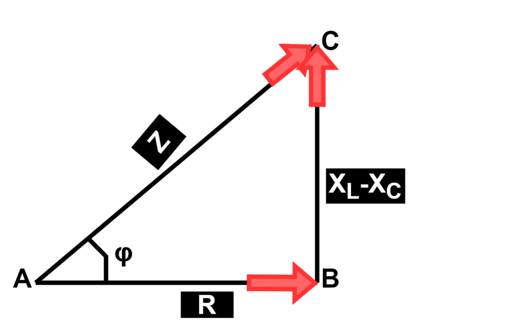
When the inductive reactance is greater than the capacitive reactance then the resultant circuit reactance is inductive and the power factor is lagging.
Case-2: when (XC > XL)
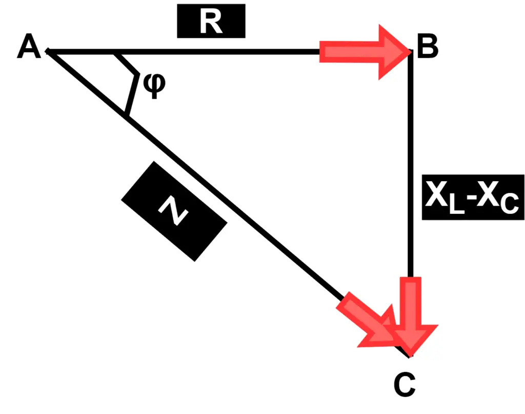
When the capacitive reactance is greater than the inductive reactance then the resultant circuit reactance is capacitive and the power factor is leading.
Applications of RLC Series Circuit
The applications of the RLC circuit are as follows.
- Variable tuned circuit
- Low pass, high pass, bandpass, and bandstop filters
- Oscillator
- Voltage multiplier
- Pulse discharge circuit
This is all about the RLC circuit.
Solved Problem on RLC Series Circuit
Example (1) – A 220 V, 50 Hz, ac supply is connected across a coil of 0.05 H inductance and 2 Ω resistance. This coil is connected in series with a capacitor of 6 µF. Determine, Impedance (Z), Current (I), Power factor (cos ϕ), and Power consumed (P).
Solution – Given data,
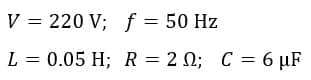
Hence, the inductive and capacitive reactances are given by,
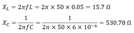
Here, XC > XL, hence this circuit will behave like a capacitive circuit.
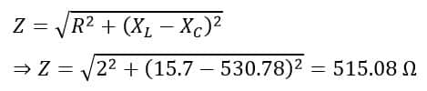
Impedance of the circuit:
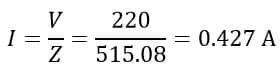
Circuit Current:
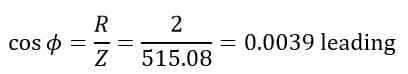
Power Factor:
Power Consumed: