A parallel RLC circuit is a type of alternating current (AC) circuit that consists of all three basic elements, namely, resistor (R), inductor (L), and capacitor (C), and all these elements are connected in parallel across a source of AC voltage.
In this article, we will study a parallel RLC circuit and analyze it to obtain different parameters such as current, voltage, impedance, admittance, etc.
What is a Parallel RLC Circuit?
As mentioned above, in a parallel RLC circuit, a resistor, an inductor, and a capacitor are connected in parallel to each other. A typical parallel RLC circuit is depicted in the following figure.
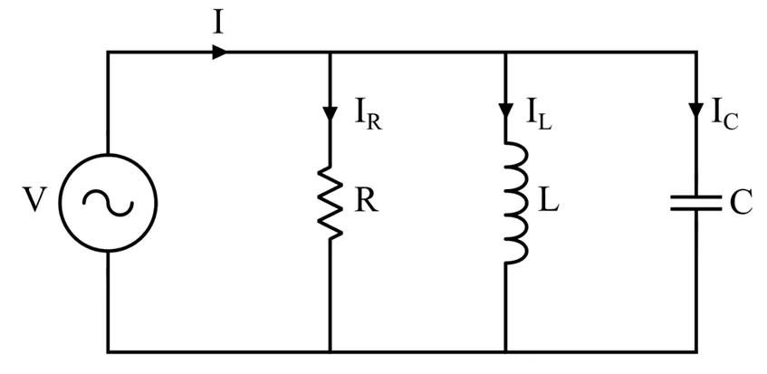
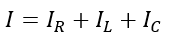
In the above circuit, a source of AC voltage V is applied across a parallel combination of resistor, inductor, and capacitor. It can be seen that the voltage across all three circuit elements is the same. But, the current flowing through each element is different, and the phasor sum of these three currents is equal to the total current drawn from the source, i.e.,
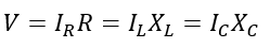
Where R is the resistance, XL is the inductive reactance, XC is the capacitive reactance, IR is the current through the resistor, IL is the current through the inductor, and IC is the current through the capacitor.
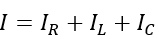
The total current through the circuit is given by,
Now, let us analyze this parallel RLC circuit to obtain expressions for different parameters.
Parallel RLC Circuit Analysis
In this section, we will derive expressions for different electrical parameters for the circuit.
(1). Phasor Diagram of Parallel RLC Circuit:
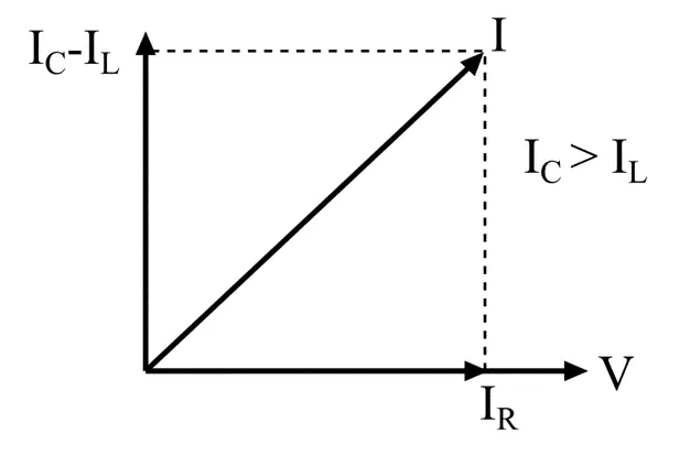
A phasor diagram is a graphical tool that shows the relationship between different electrical quantities in the circuit. The phasor diagram will take the common electrical quantity, i.e., voltage, as a reference phasor. The current phasor for the resistor is in phase with the voltage or reference phasor, the current phasor for an inductor is lagging behind the voltage phasor by 90°, and the current phasor for the capacitor is ahead of the voltage by 90°. All these are basic properties of resistors, inductors, and capacitors.
Now, there can be three possible cases as follows:
Case I – When IL < IC, the equivalent reactive current will be (IC – IL), and its phasor diagram will be shown in the following figure.
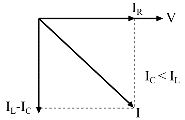
Case II – When IC < IL, the equivalent reactive current will be (IL – IC), and its phasor diagram will be as depicted in the following figure.
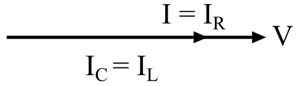
Case III – When IL = IC, the resultant current will be I = IR. The phasor diagram will be shown in the following figure.
(2). Magnitude of Current:
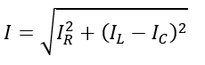
As we know, the magnitude of current in a parallel RLC circuit is obtained by calculating the phasor sum of all the three current components, i.e.,
The magnitude of circuit current is given by,
(3). Admittance of Parallel RLC Circuit:
Admittance is given by,
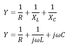
Where ω is the angular frequency of supply voltage.
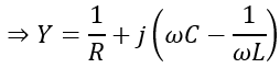
The admittance is given by,
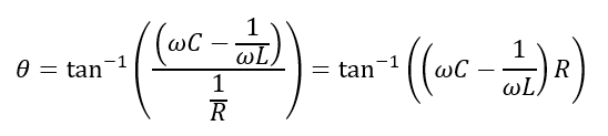
The admittance angle of the circuit is given by,
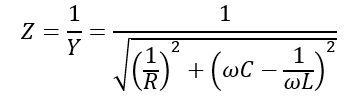
(4). Impedance:
The impedance is the total opposition that the three circuit elements offer to the flow of current. It is given by,
(5). Conductance and Susceptance:
The conductance is defined as the reciprocal of resistance, i.e.,

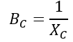
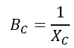
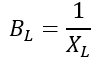
The susceptance is defined as the reciprocal of reactance, i.e.

Therefore,
Therefore,
And
Therefore, the admittance of the RLC circuit can also be given by,
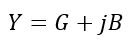
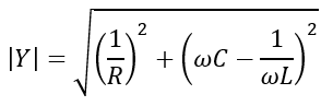
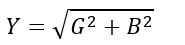
And the magnitude is given by,
(6). Admittance Triangle of Parallel RLC Circuit:
The admittance triangle of a parallel RLC circuit is shown in the following figure.
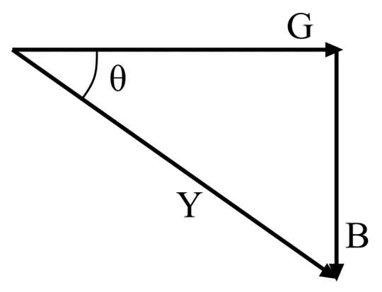
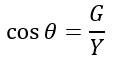
From the admittance triangle, the power factor of the circuit is given by,
Hence, all these are the important parameters of a parallel RLC circuit.
Let us now consider a numerical example to understand how to use these formulae to solve a problem.
Solved problem on RLC Parallel Circuit
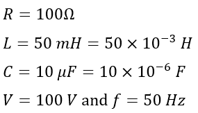
Example – A 100 Ω resistor, a 50 mH inductor coil, and a 10 µF capacitor are connected in parallel across a 50 Hz and 100 V supply. Calculate the current drawn from the source and the current through each branch. Also, calculate the impedance of the circuit and the phase angle.
Solution – Given,
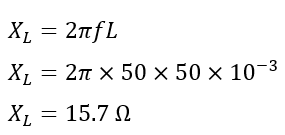
Therefore, the inductive reactance of the circuit will be,
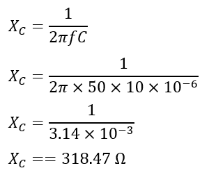
The capacitive reactance of the circuit will be,
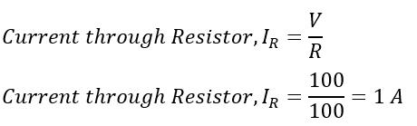
Now, the current through each branch is given by,
Current through resistor R,
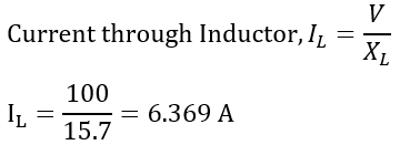
Current through inductor L,
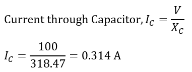
Current through Capacitor C,
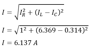
The total circuit current is given by,
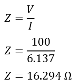
The impedance of the circuit will be,
Hence, this is all about parallel RLC circuit analysis.