An RL series circuit is one that contains two basic circuit components, namely an inductor and a resistor connected in series across an AC source. A common example of an RL series circuit is the winding of an electric motor.
In this article, we will study and analyze the RL series circuit and derive different electrical quantities used to understand the circuit’s behavior.
What is an RL Series Circuit?
An RL series circuit is an AC circuit consisting of an inductor and a resistor connected in series.
In other words, when an inductor and a resistor are connected such that the same current flows through them, it is called an RL series circuit.
A typical RL circuit is depicted in the following figure.
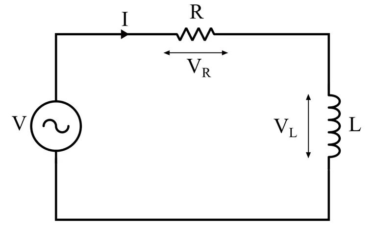
We can express the above circuit through an algebraic voltage equation. For this, let’s apply KVL to the circuit, we get,
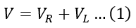
Here, V is the RMS value of supply voltage, VR is the RMS value of voltage drop across resistor R, and VL is the RMS value of voltage across the inductor L.
As we know, the voltage drop across a resistor is given by,
The voltage across an inductor is given by,
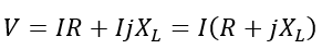
Therefore, the equation (1) can be written as

This is the standard equation of an RL series circuit connected across a source of AC voltage of V volts.
Phasor Diagram of RL Series Circuit
In an RL circuit, the current through the resistor and the inductor are the same. Hence, we can draw the phasor diagram of the RL circuit by taking the current as the reference phasor.
In a resistor, the current through the resistor remains in phase with the voltage drop across it, as represented by phasor OA in the phasor diagram shown below.
In an inductor, the current through the inductor lags the voltage across it by 90°, as represented by the phasor OB in the phasor diagram.
Hence, for a series RL circuit, the phasor diagram is the resultant of these two phasors, which is shown in the following figure.
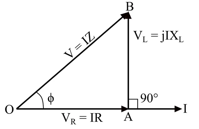
From the phasor diagram, it is clear that in an LR series circuit, the current always lags the voltage by an angle ϕ.
Electrical Quantities of RL Series Circuit
Now, let us derive expressions of different electrical quantities.
(1). Impedance of RL Series Circuit:
In an RL series circuit, there are only two circuit elements: a resistor and an inductor. Therefore, the RL circuit offers two oppositions to the flow of the electric circuit; one is due to resistance R, and another one is due to inductive reactance XL, where XL is given by,

Here, ω is the angular frequency, and f is the linear frequency of the supply source.
Therefore, the impedance Z of the circuit will be,
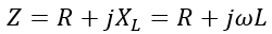
Here, the j is the complex operator, representing a phase difference of 90° between resistive and inductive components of the impedance.
It is important to note that impedance is a vector quantity with both magnitude and phase angle.
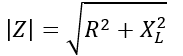
The magnitude of the impedance of the circuit is given by,
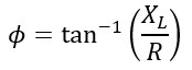
The phase angle or impedance angle of the circuit is given by,
(2). Current in an RL Series Circuit:
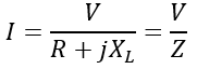
The voltage equation of an RL series circuit can also be written as,
Where I is the RMS value of the circuit current.
Rearranging this equation, we can obtain the current flowing through the circuit as follows:
(3). Power Factor
The power factor of an RL series circuit is defined as the cosine of its impedance angle or phase angle, i.e.,
From the phasor diagram, we can observe that.
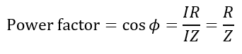
The RL circuit has a lagging power factor, and the current lags the voltage.
(4). Power in RL Series Circuit
From the basic definition of electric power, the instantaneous power is given by,
In a series RL circuit, the instantaneous powers consumed in the resistor and inductor are given by,
Therefore, the total instantaneous power consumed in the circuit is given by,
It is also important to note that the inductor consumes no average power. Therefore, the average power will be consumed by the resistor only, i.e.
Where I is the RMS value of supply current.
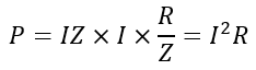
Alternatively, the average electrical power in a circuit is given by,
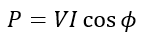
Substituting the values of V and cosϕ, we get,
Solved Problem
Now, let us consider a solved numerical example to understand the application of equations derived in this article.
Numerical Example – The winding of an electric motor has an inductance of 50 mH and a resistance of 1.5 Ω. These two elements are considered to be connected in series, forming an LR series circuit. If a voltage of 220 V is applied to this winding, calculate the current through the winding, total impedance of the winding, power factor of winding, and the average power consumed in the winding.
Solution – Given,
Voltage, V = 220 Volts
Inductance, L = 50 mH
L= 50 × 10-3 H
Resistance, R = 1.5 Ω
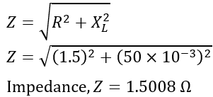
Therefore, the impedance of the winding is,
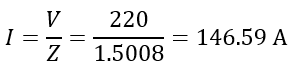
The current flowing through the winding is,
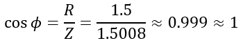
The power factor of the winding is,
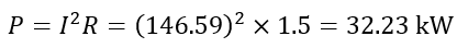
The average power consumed in the winding is,
Hence, in this article, we have covered all the essential concepts of an RL series circuit. Also, we have discussed a solved numerical example to understand the applications of equations to analyze the circuit.