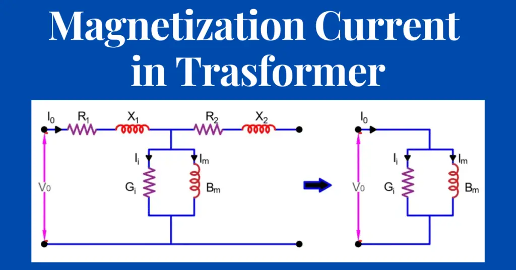
A transformer draws a certain amount of magnetization current from the source when its secondary winding is not connected to the load. This current at no load condition sets up the magnetic flux in the core and it is called the magnetization current.
Definition of Magnetization Current
When electric current flows in the primary winding of the open-circuited transformer, some part of the primary current sets up magnetic flux in the core. The electric current used for setting up the magnetic flux in the core is called magnetization current.
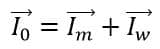
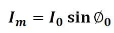
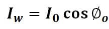
The primary current (I0) of the transformer has two components of current- magnetizing current (Im) and core loss current (Iw).
Thus,
The magnetizing current is defined at the rated voltage and rated frequency of the transformer.
Properties of Magnetization Current
- No load current of the transformer remains constant and it is not load dependent. Therefore, the loss component current (Iw) and magnetization current (Im) have fixed magnitudes irrespective of the load on the transformer.
- The magnetization current is produced by applying the sinusoidal voltage to the transformer’s primary. But, the current is not sinusoidal and distorted because of the Hysteresis.
- Magnetizing current lags the voltage by 900.
- Im is purely inductive in nature.
Now, we will discuss the procedure for the calculation of the magnetization current.
Procedure for Calculation of Magnetization Current
As we discussed, the magnetizing current is the current drawn by the transformer for setting up magnetic flux in the core. Therefore, the magnetization current, loss current, and power factor can be calculated by conducting the no-load test on the transformer.
No-Load Test
This test is carried out on the transformer to determine the following performance parameters of the transformer.
- No-load Loss
- No-load current
- Magnetization Current
- Load Loss current
- Turns ratio
No-load Test Circuit
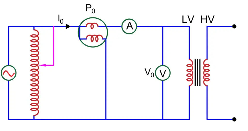
to calculate magnetization current, we need to carry out this test by applying the full rated voltage to either primary or secondary. For convivence and to avoid HV for testing, rated voltage is applied to the LV side of the transformer, keeping the HV side of the transformer open. The measuring instruments ammeter, voltmeter, and power meter are connected as shown in the below diagram.
Procedure
- Apply voltage to the LV side of the transformer through the autotransformer. Increase the voltage till the rated voltage is applied to the LV winding.
- The voltmeter shows the voltage applied to the LV side. Ensure that this voltage should be equal to the rated voltage of the LV side of the transformer.
- The ammeter reading shows the no-load current (I0).
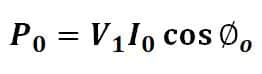
- The power meter reading(P0) shows the no-load loss in the transformer.
- Measure the HV side voltage of the transformer for calculating the turn ratio of the transformer. CAUTION: The voltage at the HV side is very high, and suitable PT should be used to step down the voltage.
- Now, we can use the readings of the voltmeter, ammeter, and power meter to calculate transformer core loss and magnetization current.
Calculation of Core Loss and Magnetization Current
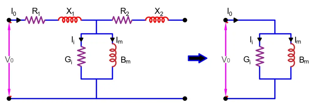
We can neglect the ohmic losses in the winding resistance and reactance because of a very low magnitude of current flows through the LV side of the transformer. So, we calculate the core loss and core loss current neglecting the copper loss.
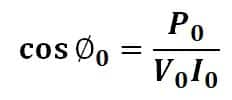
Power factor of the transformer at no load
Magnetizing current of the transformer
Core loss component of current of the transformer
No-load loss of the transformer
Where Im is the magnetization current and Iw is the core loss component.