The transformer draws no load current from the supply source when its secondary is open circuit. The no-load current has two components: magnetization current(Im) and iron loss component current(Iw). The transformer takes a magnetization current to set up the magnetic flux in the CRGO magnetic core. The iron loss component of the current caused by eddy current and hysteresis current and the current remains fairly constant with change in loading on the transformer. The phasor diagram of the transformer at no load is given below.
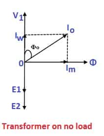
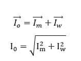
When the transformer is at no load, no current flows from the secondary side of the transformer, and no de-magnetizing flux is generated from the secondary side MMF, and the transformer will draw only the no-load current from the supply source. The major portion of the no-load current(Io) has a magnetization current(Im). The magnetization current lags the primary voltage by 90 electrical degrees. The no-load current(Io) is the vector sum of the magnetization current(Im) and the working current(Iw).
The cosine of the angle between the applied voltage(V1) and the no-load current(Io) is the power factor of the transformer at no load.
The angle between the applied primary voltage and the primary current(I1) gets reduced when the load on the transformer is increased. Let us understand how the phase angle between primary voltage and primary current reduces with an increase in the secondary current.
The secondary current sets up its magneto motive force, which opposes the primary MMF, and thus, the net MMF of the transformer remains fairly constant. In other words, we can say that the transformer operates at constant flux density for the rated voltage and frequency.
The phasor diagram of the transformer at load is given below.
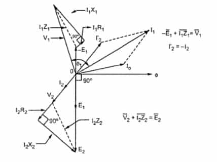
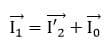
The secondary current (I2) is reflected in the primary side of the transformer, and the primary current is equal to the vector sum of the no-load current, and the secondary current refers to the primary side of the transformer.
The phase angle between the primary voltage (V1) and the primary current(I1) gets reduced with increased loading on the transformer, and thus, the power factor of the transformer gets improved. In case there is some loading in the transformer’s secondary winding, some more current will be drawn from the source to compensate for the demagnetizing effect of the secondary current. So now the net primary current would contain ‘NO LOAD CURRENT’ + ‘EXTRA COMPENSATING CURRENT( Equal to secondary current) ‘and as a result, it would shift the net current phasor more towards the voltage axis and would result in the improvement of the power factor.
good and useful