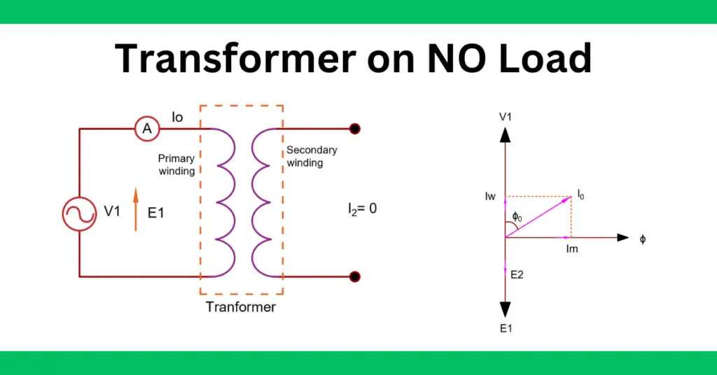
A transformer on no load means its secondary winding is not connected to the electrical load and the current in the secondary winding is zero. The primary winding draws a small current for setting up magnetic flux in the core and to meet iron loss in the transformer. The primary current on load is about 2 to 10 % of the rated current, and this current is called no-load current I0.
The no-load current I0 supply hysteresis and eddy current loss and a small amount of copper loss. Also, no load current supplies the magnetization current Im for setting up the magnetic field in thecore of the transformer.
The nature of the current is inductive when a transformer is at no load. It means the no-load current lags behind the applied voltage by a large electrical degree and as a result, the power factor of the transformer is very low, in the range of 0.1 to 0.2.
Components of current of No-load Transformer
There are two components of the no-load current. These are,
Reactive or Magnetizing Component Im
The primary winding is made of copper or aluminum and it has a large value of inductance and a small value of resistance. when voltage V is applied to the primary winding, it draws inductive current and lags behind the voltage by 90 electrical degrees. This current is called magnetization or magnetizing current. The power drawn by the magnetizing current is zero because the phase difference between voltage and current is 900.( P= VICosΦ= VI X Cos 90= VI X 0 =0)
The magnetizing current Im sets up the magnetic flux in the core under the transformer at no-load or full load.
Active or Power Component Iw
The transformer at no-load draw an active current to supply eddy current, hysteresis, and some amount of copper loss. The eddy current loss occurs in a transformer because of eddy current sets up in the core. The heat loss in the core because of eddy current is called eddy current loss. The hysteresis loss occurs because of cyclic magnetization with lagging characteristics of the B-H curve.
Active current Iw is in phase with the applied voltage.
You can better understand the transformer on no-load with the phasor diagram of the transformer.
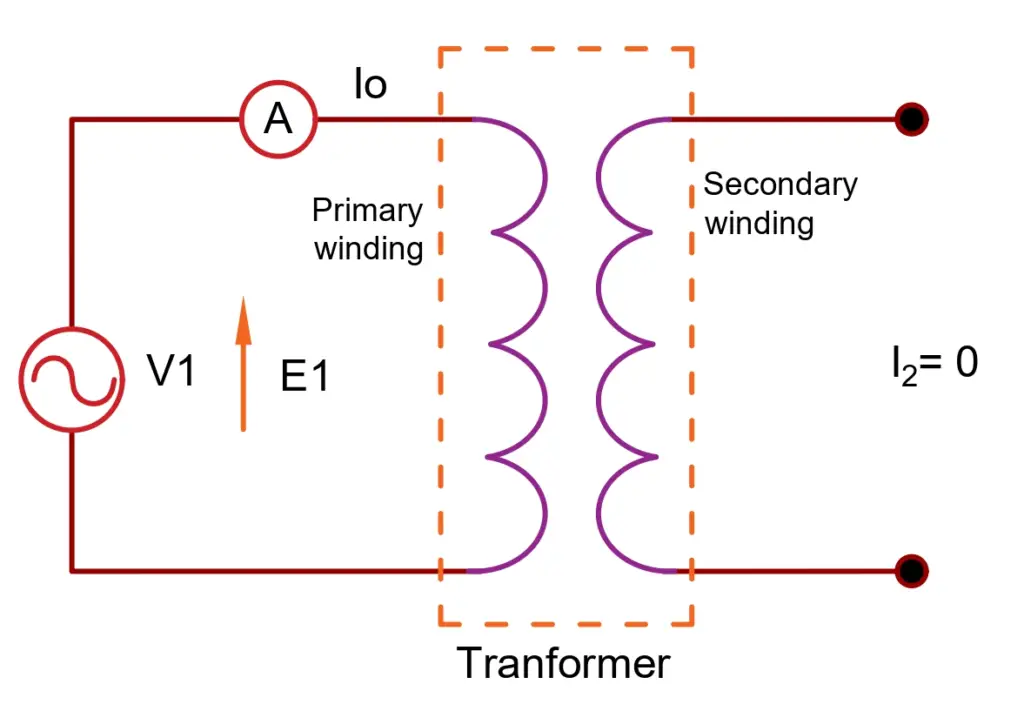
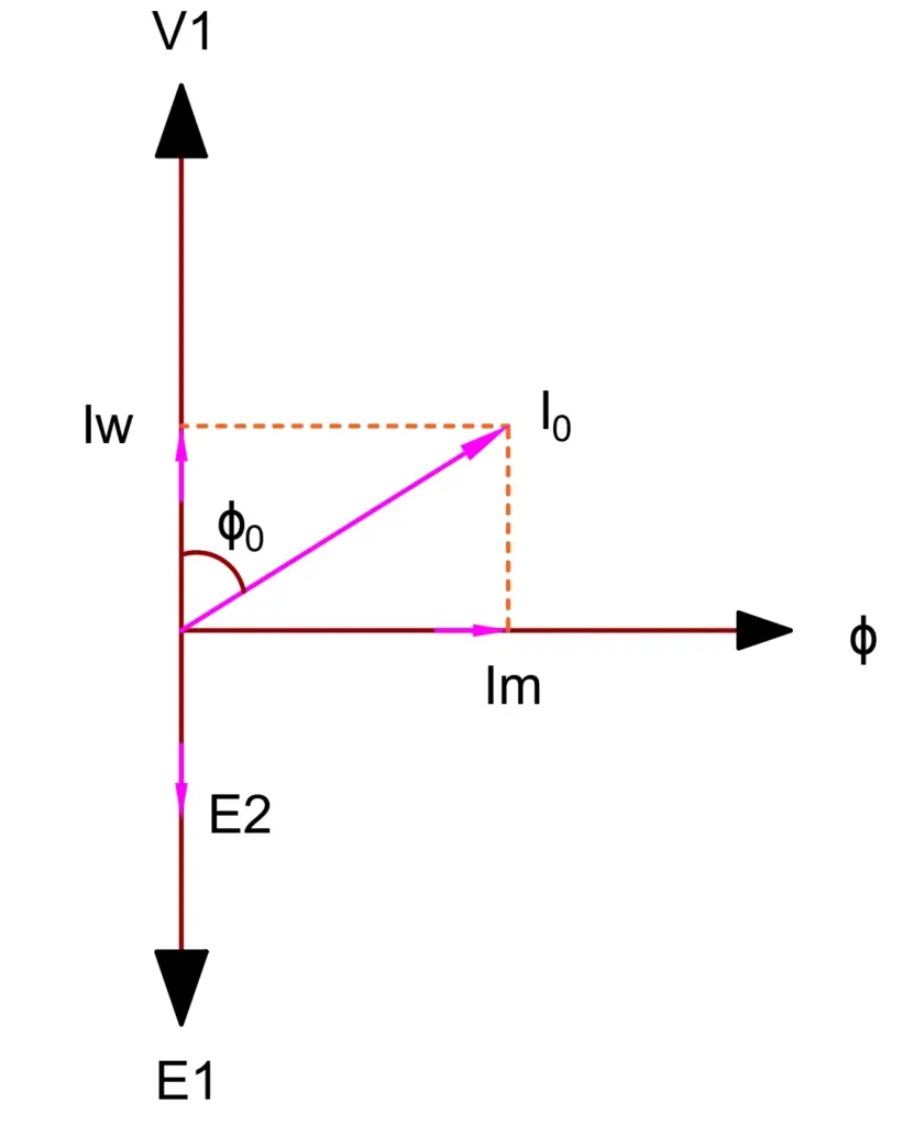
Steps to Draw the Phasor Diagram of Transformer on no-load
- The magnetization current sets up the magnetic flux in the core. The magnetization current is purely inductive in nature. Therefore, the magnetization current Im lags the applied voltage V1 by 90 degrees. Thus, the magnetization current Im and flux ϕ is in phase.
- The magnetic flux induces the EMF in the primary and secondary winding that opposes the applied voltage. Therefore, induced EMF E1 & E2 lags the applied voltage by 180 degrees and lags the flux ϕ by 90 degrees.
- The no-load current of the transformer is very low, therefore primary copper loss is neglected.
- The current in the secondary winding is zero, therefore copper loss in the secondary is zero.
- The no-load loss components are in phase with voltage V1, and therefore no load loss current Iw is in phase with V1.
- No-load current I0 lags the applied voltage V1 by ϕ0 degrees. The angle ϕ0 is the power factor angle.
- The induced EMF E1 is drawn equal and opposite to the applied voltage V1 because at no-load induced EMF is approximately equal to the applied voltage.
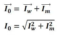
- The vector sum of the magnetizing current Im and no-load loss current Iw of the transformer is equal to the no-load current I0.
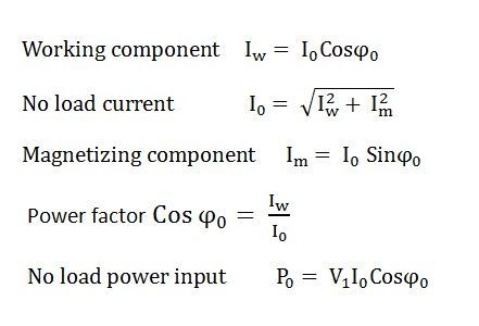
From the above phasor diagram, we can make the following conclusions.
Working Component Iw of no-load current
Magnetizing Component Im of no-load current
No-load current of Transformer
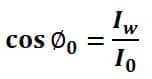
Power Factor of Transformer on no-load
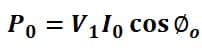
No load Input Power