A vector diagram of transformer represents the phasor relationships between a primary and secondary voltages and currents. It is an important tool for understanding the transformer’s working performance under various operating and fault conditions.
This article describes the vector diagram of a transformer. Here, we will study how to draw a vector diagram of a transformer with the help of examples.
What is a Transformer?
A transformer is an electrical machine that consists of two magnetically coupled electrical circuits to transform and transfer electrical energy from one circuit to another with a different voltage and current level.
The main parts of a transformer are primary winding, secondary winding, and magnetic core. The primary winding receives input electrical energy and the secondary winding produces transformed electrical output. The magnetic core provides a magnetic coupling between the primary and secondary windings.
What is a Vector Diagram?
There is a graphical tool called vector diagram which is used to represent and study the phasor relationships between the primary and secondary winding EMFs, voltages, and currents of a transformer. It is also called a phasor diagram. A vector diagram is a crucial tool employed for understanding the behavior and performance of an electrical transformer under various load and fault conditions.
For a transformer, the vector diagram is a phasor diagram that provides information on phasor relationships between primary and secondary winding quantities. It also shows the phase information and polarity of both windings.
Significance of Vector Diagram of Transformer
With the help of a vector diagram of a transformer, we can easily compute and determine the following parameters of the transformer:
- Electrical circuit parameters of the transformer such as winding resistance, reactance, impedance, and electrical losses.
- The efficiency of the transformer for different operating conditions.
- Over-load and short-circuit analysis of the transformer.
- Determine the fault values of the transformer such as open circuit fault current, short circuit fault current, etc.
- Determine the rating of the auxiliary devices like circuit breakers, fuses, relays, etc.
- Verifying connections and polarities of the transformer windings in the circuit.
Information Required to Draw the Vector Diagram of a Transformer
The following information and parameters are required to draw the vector diagram of a transformer:
- Primary and secondary winding rated currents.
- Type of winding connection or configuration of the transformer windings.
- Vector Group, phase shift, and polarity of the transformer windings.
- Impedance and power factor of the load connected or expected to connect to the transformer.
How to Draw Vector Diagram of a Transformer?
The step-by-step procedure to draw the vector diagram of a transformer is explained below:
Step (1) – Draw the primary winding’s voltage phasor/vector ‘V1’. Take its length proportional to the RMS value of the primary winding voltage.
Step (2) – Draw the vector of the secondary winding voltage, and label it as ‘V2’. Take a length of this vector is proportional to the RMS value of the voltage and its phase angle as per the vector group of the winding.
Step (3) – Draw the vector for primary winding current ‘I1’. Take its length directly proportional to the RMS value of the primary winding current and the phase angle according to the primary winding power factor.
Step (4) – Draw the vector for secondary winding current ‘I2’. Take its length proportional to the RMS value of the secondary current and phase angle according to the load power factor.
After this step, the final vector diagram of the given transformer will be obtained. Using this vector diagram, we can analyze the behavior of the transformer.
Now, let us draw a vector diagram of a given practical transformer for a practical inductive load.
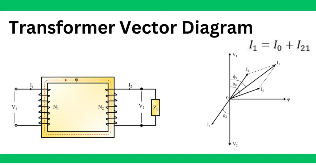
Vector Diagram of a Transformer
Consider a practical transformer having a load impedance ZL connected to its secondary winding as shown in the following figure.
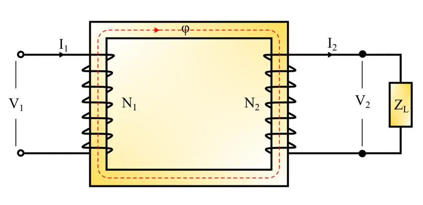
This transformer has the following specifications:
V1 = Rated primary winding voltage
V2 = Rated secondary winding voltage
I1 = Rated primary winding current
I2 = Rated secondary winding current
Calculations:
Since we have taken an inductive load, hence the secondary current I2 will lag the secondary winding voltage V2 by a phase angle say φ2.
The total primary current I1 is given by,
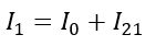
It is the phasor sum. Where I0 is the magnetization current and I21 is current to balance the counter effect of the secondary winding current I2.
Therefore, for the operating condition of the transformer, primary winding MMF and secondary winding MMF must be equal, i.e.
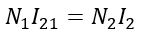
Therefore,
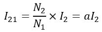
Where a is the transformation ratio of the transformer.
Since the current I21 is current in the primary winding to balance the counter effect of secondary winding current I2. Therefore,
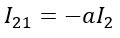
Hence, the current I21 is 180° out of phase with the current I2.
Vector Diagram:
The vector diagram of this transformer is shown in the following figure.
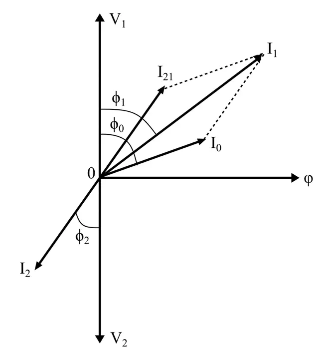
Here, V1 and V2 are out of phase with each other. The voltage V2 is lagging the main flux φ (reference axis) by 90°. The current I21 represents the primary winding current that balances the effect of the secondary winding current I2. Hence, the secondary current I2 is represented in the antiphase with the current I21. The current I0 is the no-load current lagging the input voltage V1 by angle φ0. The phasor sum of the currents I0 and I21 gives the total primary winding current I1.
Hence, this is all about drawing a vector diagram of a transformer.