In this post, we shall discuss different types of Relays like Latching Relay, Reed Relay, Solid State Relay, Differential Relay, Automotive Relay, Timer Delay Relay, Reed relay, Polarized Relay, and many more. We will learn the Classification of Relays according to applications as well.
Table of contents
Types of Relays
There are different types of relays like:
- Electromagnetic Relays
- Latching Relays
- Electronic Relays
- Micro-processor based Relays
- Non-Latching Relays
- Reed Relays
- Check synchronizing Relays
- Reverse Power RelayS
- Generator Protection Relay
- High-Voltage Relays
- Small Signal Relays
- Time Delay Relays
- Multi-Dimensional Relays
- Thermal Relays
- Differential Relays
- Distance Relays
- Vector Surge Relay
- Under Voltage Relay
- Automotive Relays
- Frequency Relays
- Polarized Relays
- Rotary Relays
- Sequence Relays
- Moving Coil Relays
- Buchholz Relays
- Safety Relays
- Supervision relays
- Ground Fault Relays
- df/dt Relay
The relays are most important for controlling and protecting the electrical system. The relay are used according to the application requirement.
Latching Relays
A latch means maintaining the position or locking the position. The latching relay maintains its state after being actuated. We also call latching relays Impulse Relays or Keep Relays or Stay Relays.
The internal magnet in a latching relay holds the contact. on energizing the coil, it holds the contact position, and hence now it does not require power to maintain its position. The relay remains in its state after the removal of the drive current. Thus, it is possible to save considerable energy.
Types Of Latching Relay
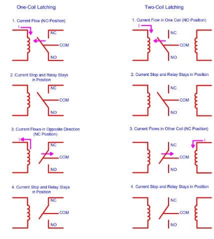
Latching relays have one or two coils, and these coils are responsible for the position of the armature of the relay. Hence, latching relays don’t have any default position as shown in the above figure.
There are three main types of Latching relays. Magnetic latching, Mechanical Latching, and Impulse Sequencing.
In one coil type relay, the armature position depends on the direction of current flow in the coil. In the case of two coil types, the position of the armature is dependent on the coil in which current flows. These relays maintain their position once actuated, but their reset position depends on the control circuitry.
Reed Relay
Reed relays are one types of relay which are similar to the electromechanical relay. It also produces the mechanical movement of physical contacts to open or close a circuit path. The contacts rating of the reed relay is much less than the electromechanical relay.
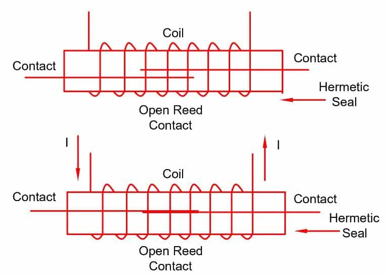
The coil of the relay wounded around a reed switch. The reed switch acts as an armature of the relay. The relay has a glass tube or capsule filled with inert gas with two overlapping reeds (or ferromagnetic blades). All the components of the relay has hermetically sealing.
The overlapping ends of a reed relay have its connection in such a way that we can connect the input and output terminals easily. When the coils receive the power, it sets up magtnetic field. The magnetic field draws the reeds together. And, thereby their contacts make a closed path through the relay. During the de-energizing process of the coil, the pulling force of the spring attached to them separates the reeds.
The switching speed of the reed relay is more than an electromechanical relay. It takes 1/10 th times in the actuation of the electromechanical relay. The main reason for it is the less massive, different actuating medium and smaller contacts. However, arcing problem due to smaller contacts happens in the reed relay.
The arcing on the contact surface may melt the small section of the contact area. Finally, this leads to contact welding. Thus, the contact remains closed even after the de-energization of the relay.
By placing series impedance like a resistor or ferrite between the relay and system capacitance, we can control the arcing problem. The impedance limits the inrush currents, thereby avoiding any arcing in the relay.
Read More : What is protective Relay | its working Principle
Polarized Relay
Polarized relays are very sensitive to the direction of the current by which it gets energization. There are two types of polarized relays – permanent & electromagnet types. The armature moves according to the net magnetic force of the electromagnet & permanent magnet.
These relays use magnetic forces instead of spring forces to attract or repel the armature. The armature is a permanent magnet that has pivotal movement between the pole faces. The electromagnet forms the pole faces. The electromagnet produces a magnetic flux when the current flows through it.
Working Principle of Polarized Relay
Whenever current flows in the electromagnet, it exerts a force on the armature. Thus, the force exerted by the electromagnet exceeds the force exerted by a permanent magnet. As a result, the armature changes its position. In a similar way, electromagnetic force reduces less than that of the permanent magnet during current interruption. And, thus the the armature returns to its original position.
The magnetic flux Φm produced by the permanent magnet divides into two parts in Φ1 and Φ2. The flux Φ1 passes through the left working gap of the magnet, while Φ2 passes through the right working gap of the magnet.
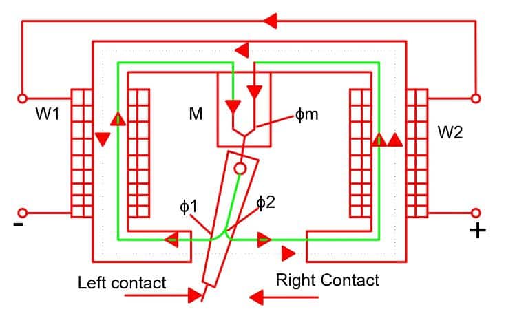
The armature will stay either at the left or right of the neutral position due to these two fluxes when no current flows through the coil. It is because the neutral is not stable in such magnetic systems.
When the coil of the relay receives current, an additional working magnetic flux Φ passes through the working gap of the magnet. The two magnetic forces interact and it exerts the force on the armature. The exerted force depends on;
- Magnitude of the current
- Polarity of the current
- Initial position of armature
- Additional magnetic flux
Depending on the above parameters, the armature of the relay turns to a new stable state, and thereby closes the right contact and hence the relay picks up.
The two most popular types of polarized relays are differential and bridge type relays.
Buchholz Relays
The Buchholtz relays are gas-operated or actuated relays. These types of relays are suitable for detecting incipient faults in the transformer. Buchholtz relays are most important for oil-filled transformer protection. The relay is fitted in between the transformer tank and the conservator.
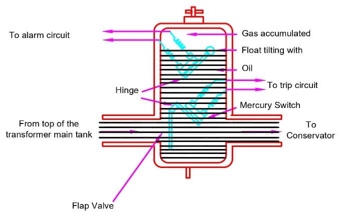
When incipient faults happen inside the transformer, the gas evolves & the oil level falls. This causes the hollow top float to tilt and mercury contacts to close. Thus, the relay initiates the alarm, which shows that there is a minor internal fault inside the transformer.
In the case of major faults like a short circuit in transformer winding or internal connections, the pressure inside the transformer abruptly increases, and that causes drop in the oil level. Thus, the decrease in the oil level causes the bottom flap valve to operate. The bottom float valve cause the mercury switch to close and the relay trips the upstream and downstream breakers
Overload Protection Relays
Overload protection types of relays provide the over-current protection of electrical motors. There are two types of overload relay- bimetallic strip type & Electronic relay.
The relay that functions on the principle of heat measurement consists of a coil that heats up a bimetallic strip. When current flows through the bimetallic relay the strips heat up. When the heating effect is more than the set current of the motor, the bimetallic strip bends and thus makes the contact open. The motor trips with overload fault when the relay contact changeovers from NC to NO.

We can use the motor thermal curve for accurately setting the current and trip class in the overload relay.
The electronic overload types of relays have better performance than the bimetallic relay. The bimetallic relay has the aging effect and its accuracy drifts with the number of overloads.
Solid State Relays (SSRs)
Solid-state types relays do not have moving parts in them. The solid-state relay uses the semiconductor devices such as BJTs, thyristors, IGBTs, MOSFETs, and TRIACs to perform the switching operation. The solid-state relay has a large power gain and it we can use it for both AC and DC supply. It needs very little power for its actuation. The control energy requirement is much lower in comparison to the controlled power.
The switching speed of the solid-state relay is very high as compared to electromechanical relay. This is because the solid-state relay does not have any moving parts. A solid-state relay SSR has an electronic sensor that provides galvanic/ optical isolation.
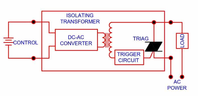
SSRs are classified on the basis of the coupling of the input signal to the relay component. These are- optically coupled SSR and transformer-coupled SSR. A small DC current is supplied to the primary of the transformer through a DC to AC converter because the transformer functions with the AC supply.
The AC is stepped-up to operate the solid-state device as well as the triggering circuit. The transformer coupling is also known as galvanic isolation.
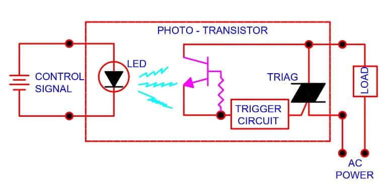
In the case of photo-coupled SSRs, The photosensor is the main element. The photosensor has a LED and phototransistor. The LED receives the control signal current and emits the light. The light incidents on the phototransistor and transistor start conducting. The transistor current triggers the TRIAC and the Triac switch on/off the controlled device. The photo isolation is relatively much better than the transformer-coupled SSR.
The SSR has a longer life because there are no moving parts in it. Also, the switching speed of the SSR is much faster than an electromechanical relay.
Inverse Definite Minimum Time Relays (IDMT Relays)
These types of relays have two types of characteristics. One is a definite time and the other is an indefinite time characteristic. When the fault current is very high, the relay trips the breaker immediately following the definite time characteristic. For lower fault current, the relay follows the IDMT characteristics. These types of the relay are most suitable for protection of the protection of distribution lines.
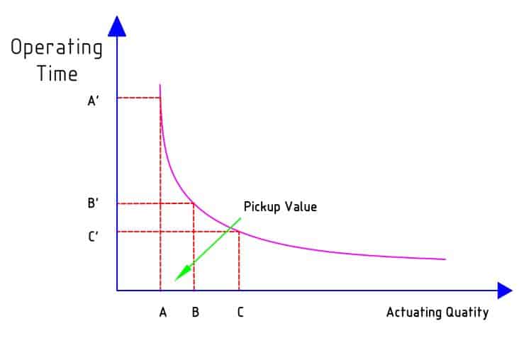
In the IDMT relay, the operating time of the relay is inversely proportional to the fault current near the pickup value and becomes constant slightly above the pickup value of the relay.
The pickup value is the point when the fault current initiates the relay to operate. The relay time does not approach zero when the measured quantity reaches its infinity value.
The relay gives inverse time characteristics at lower values of the fault current, and, it gives definite time characteristics at higher values of the fault current. The operating time becomes constant for the infinite value of the fault current.
Differential Relay
We use the differential relay for unit or zone protection. The relay monitors the magnitude and phase angle of the entering and leaving current from the equipment. It trips the breaker if any anomalies are found in the incoming and outgoing current.
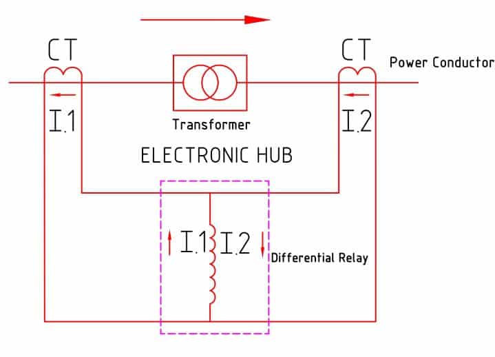
The differential relay monitors the current of the primary and secondary sides of the transformer, generator. The primary and secondary current is equal in phase and magnitude when there is no fault in the transformer. The relay trips when there is a fault inside the equipment. The relay remains inoperative in all the cases of external fault.

The differential relay detects the fault in a particular area. These types of relays are used for differential protection of transformer and generator.