A pull up resistor is a passive element used in various digital electronic circuits to provide a reliable signal level. It is mainly used to provide a default logic level to a signal line, in the cases where the signal line cannot be driven by an external signal.
In a digital circuit, the pull up resistor is usually connected between a power supply and the signal line and it ensures that the signal line receives a proper signal level.
What is a Pull-up Resistor?
A pull up resistor ensures a known state for a signal, either logic 1 or 0. It is used with transistors and switches. On opening or closing of the switch, the pull-up resistor maintains the voltage either high or low at the input or output pin of a digital device. The pull up resistor is like a simple resistor that opposes the flow of electric current.
The digital circuit functions on logic 0 or logic 1. What is the range of voltage levels for logic 1 and 0? The logic level depends on the type of digital device, TTL or CMOS.
Let a digital circuit operate at 5 Volts. The voltage level between 2 to 5 volts is a high state for TTL digital devices, and 0.8 to 0 Volts is a low state.
If the voltage at the input pin is 0.9 to 1,9 volts, the circuit can not decide the signal is whether high state or low state. This is the floating state condition. The pull up resistor eliminates the floating state condition and we can have a reliable operation of digital circuits.
Importance of Pull Up Resistors in Digital Circuits
In a digital circuit, the digital signals are specified by different levels of voltage. For example, the HIGH or Logic 1 state of a digital signal is specified by a voltage level nearly equal to the supply voltage, on the other hand, the LOW or Logic 0 state of the digital signal is specified by a voltage level equal to ground voltage (0 V).
Whenever a signal line of a digital system is left open or unconnected to a source, it is said to be in a floating condition. Under the floating condition, the signal line may pick up a noise signal and can exhibit undesirable behavior, which has to be prevented.
Therefore, we can use a pull-up resistor between the supply voltage and the signal line to avoid the floating condition and prevent the undefined behavior of the system. This will pull the signal line towards a HIGH state, i.e. in the absence of an active driving source, the pull-up resistor provides a logic 1 state to the signal line.
How Does a Pull Up Resistor Work?
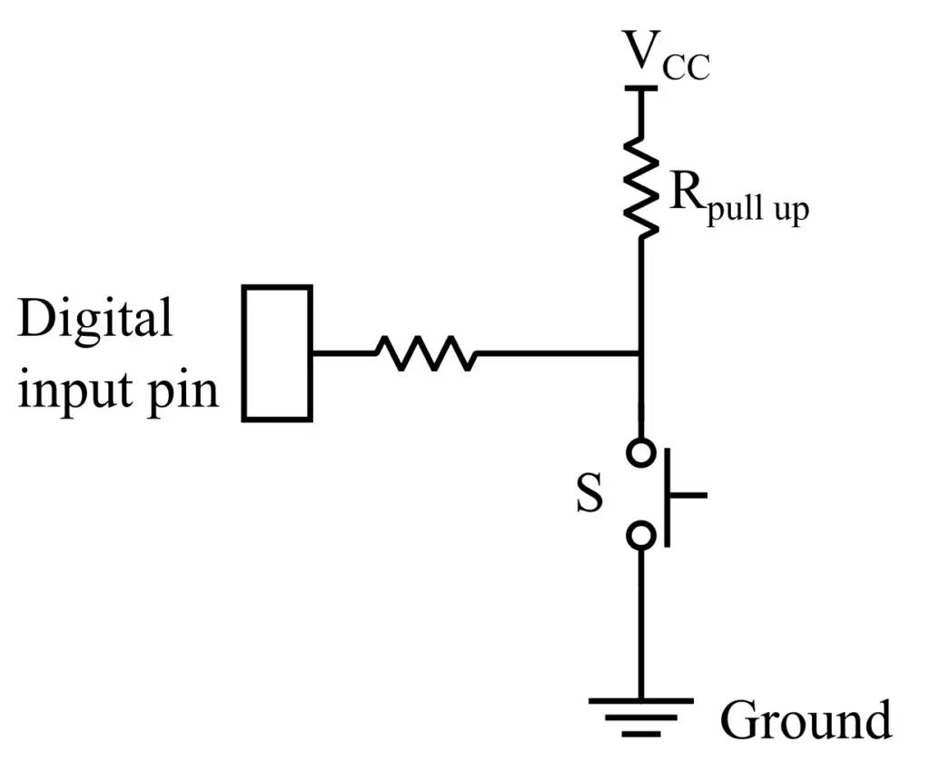
The following circuit diagram illustrates the use of a pull-up resistor in a digital circuit. Here, it can be seen that the pull resistor is connected between the supply voltage and the signal line. The circuit diagram of pull-up resistor arrangement is shown in the below image.
Now, let us understand the working of the pull up resistor.
When the switch ‘S’ is open, i.e. OFF, the input voltage is pulled up to the level of the supply voltage. When the switch is closed, i.e. ON, the input voltage is directly connected to the ground. The switch may be of mechanical or electronic type. In this way, the pull up resistor protect the signal line from floating condition and ensures a reliable voltage level.
From the above circuit diagram, it is also clear that the pull up resistor prevents the short circuit due to the direct connection between supply voltage and ground. It also protects the nuisance operation of the device caused by noise.
How to Calculate Pull Up Resistor Value?
We can apply Ohm’s law to calculate the resistance value of the pull-up resistor. The following equation can be used to estimate the resistance value of the pull-up resistor,
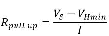
Where VS is the supply voltage, VHmin is the minimum voltage required for a valid HIGH state, and I is the current to be flowing through the resistor.
Let us understand this with an example.
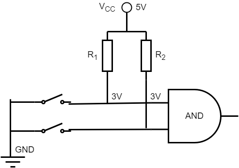
Suppose, you want to keep the 3 volts as a minimum voltage for the logic high. Let the current through the resistors are 150 µA. Then, the value of the pull up resistor is;
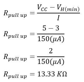
The pull-up resistor value is 13.33 KΩ.
Advantages
The following are some major advantages.
- They provide a stable logic state when no active driving source is connected to the signal line.
- Prevents the floating condition of signal and undesirable behavior of the system
- Improves the stability of the digital system.
- Improves the signal integrity by providing a stable logic level.
- They improve the noise immunity of the system and avoid undefined behavior of the system caused by external electromagnetic interference.
- Helps in creating compatibility and providing an interface between different devices.
- They are highly energy efficient and ensure proper logic levels with minimum power consumption.
Applications of Pull-Up Resistor
The pull-up resistor is used in a variety of digital circuits to ensure a reliable logic level. The following are some key applications.
- Widely used in different digital circuits to provide a digit input to them
- They are also employed to create a smooth interface between a switch and a digital system.
- Used in digital input circuits of microcontrollers to ensure a stable logic state.
- They are used in I2C communication to ensure reliable communication between different devices.
- They are commonly used in bus systems to provide proper bus termination.
Conclusion
Hence, this is all about the pull-up resistor, its working, and its application. In conclusion, this resistor is an essential component in digital circuits to provide a stable logic level and enhance the noise immunity of the system. It mainly prevents the floating condition of the signal line in a digital circuit.