In digital electronics, a multiplexer, also known as MUX, is a combinational logic circuit widely used in various operations, such as data selection, route signals, decoding addresses in microcontrollers, and more.
Multiplexer is one of the crucial components of a communication system used to transmit multiple signals of a communication channel. This article describes the multiplexer, its block diagram, types, truth table, and applications. So, let’s start with the basic definition of the multiplexer.
What is a Multiplexer?
A multiplexer is a combinational logic circuit with several input lines and only one output line. It also has multiple control lines or select lines, depending on the number of input lines.
The block diagram of a multiplexer is displayed in the following figure.
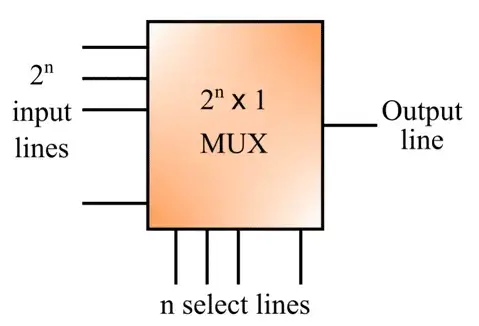
A multiplexer is also known as a data selector, as it accepts multiple signals at a time and selects one of them to transmit to the output. This is sometimes also known as a many-to-one logic circuit.
The function that a multiplexer performs is called multiplexing. There are several types of multiplexing present such as time-division multiplexing, frequency-division multiplexing, and wavelength-division multiplexing. Multiplexing is one of the important processes in data communication.
Types of Multiplexers
Based on construction, the following four types of multiplexers are very commonly used:
(1). 2×1 Multiplexer
A multiplexer with two input lines, one output line, and one select line is referred to as a 2×1 multiplexer. The block diagram of a 2×1 multiplexer is depicted in the following figure.
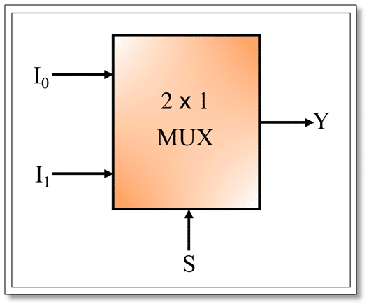
A 2×1 multiplexer is one of the simplest types of multiplexer.
Truth Table of 2×1 MUX
The truth table of a 2×1 MUX is given below:
| Input (S) | Output (Y) |
| 0 | I0 |
| 1 | I1 |
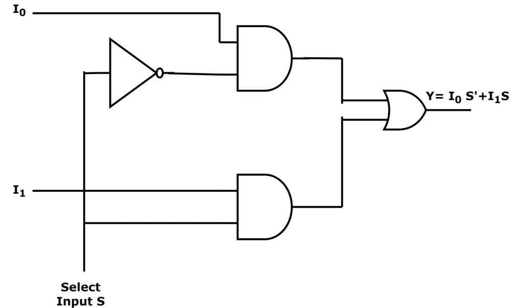
The logical expression of the term Y is ;
Y=S0‘.I0+S0.I1
The circuit of the above logical expression is given below:
(2). 4×1 Multiplexer
A multiplexer which is having four input lines, one output line, and two select lines is called a 4×1 multiplexer. The block diagram of a 4×1 multiplexer is depicted in the following figure.
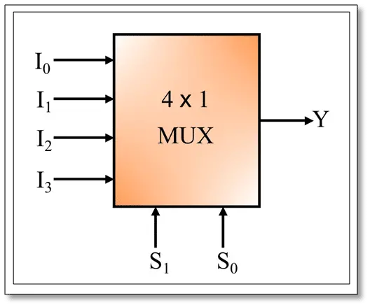
Truth Table of 4×1 MUX
The following table is the truth table of a 4×1 multiplexer:
| Inputs | Output | |
| S1 | S0 | Y |
| 0 | 0 | I0 |
| 0 | 1 | I1 |
| 1 | 0 | I2 |
| 1 | 1 | I3 |
The logical expression of the term Y is;
Y=S1‘ S0‘ I0+S1‘ S0 I1+S1 S0‘ I2+S1 S0 I3
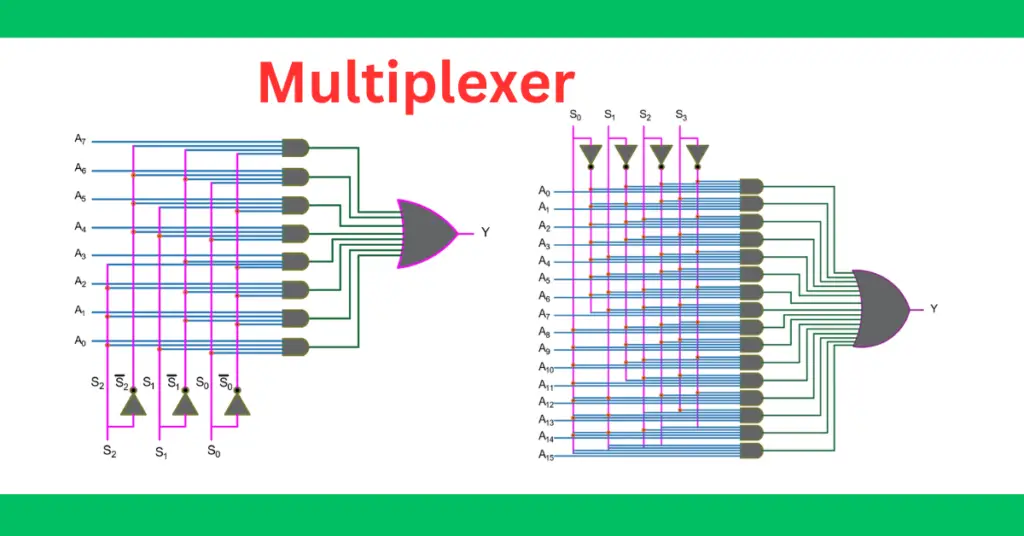
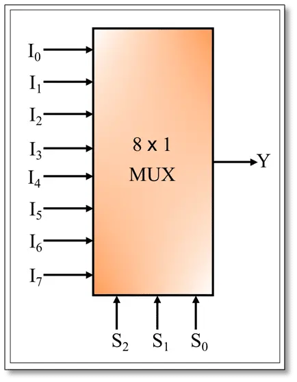
(3). 8×1 Multiplexer
A multiplexer that has eight input lines, one output line, and three select lines is called an 8×1 multiplexer. The block diagram of an 8×1 multiplexer is shown in the following figure.
Truth Table of 8×1 MUX:
The following table is the truth table of an an8×1 multiplexer:
| Inputs | Output | ||
| S2 | S1 | S0 | Y |
| 0 | 0 | 0 | I0 |
| 0 | 0 | 1 | I1 |
| 0 | 1 | 0 | I2 |
| 0 | 1 | 1 | I3 |
| 1 | 0 | 0 | I4 |
| 1 | 0 | 1 | I5 |
| 1 | 1 | 0 | I6 |
| 1 | 1 | 1 | I7 |
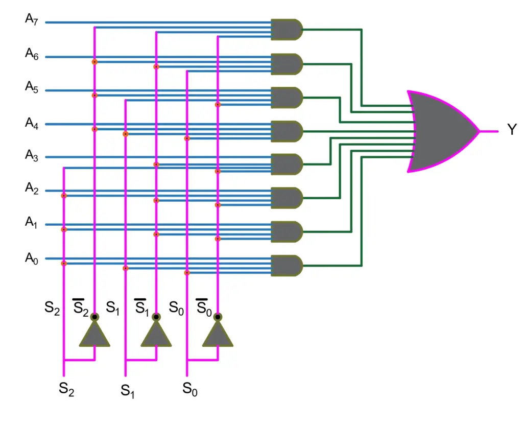
The logical expression of the term Y is,
Y=S0‘.S1‘.S2‘.I0+S0.S1‘.S2‘I1+S0‘.S1.S2‘.I2+S0.S1.S2‘.I3+S0‘.S1‘.S2 I4+S0.S1‘.S2 I5 +S0‘.S1.S2 .I6+S0.S1.S3.I7
The logic circuit of the above expression is ;
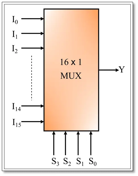
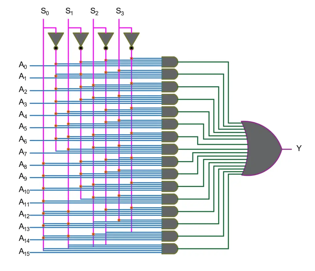
(4). 16×1 MUX
A multiplexer consisting of sixteen input lines, one output line, and four select lines is called a 16×1 multiplexer. The block diagram of a 16×1 multiplexer is shown in the following figure.
Truth Table of 16×1 MUX:
The following table is the truth table of a 16×1 MUX :
| Inputs | Output | |||
| S3 | S2 | S1 | S0 | Y |
| 0 | 0 | 0 | 0 | I0 |
| 0 | 0 | 0 | 1 | I1 |
| 0 | 0 | 1 | 0 | I2 |
| 0 | 0 | 1 | 1 | I3 |
| 0 | 1 | 0 | 0 | I4 |
| 0 | 1 | 0 | 1 | I5 |
| 0 | 1 | 1 | 0 | I6 |
| 0 | 1 | 1 | 1 | I7 |
| 1 | 0 | 0 | 0 | I8 |
| 1 | 0 | 0 | 1 | I9 |
| 1 | 0 | 1 | 0 | I10 |
| 1 | 0 | 1 | 1 | I11 |
| 1 | 1 | 0 | 0 | I12 |
| 1 | 1 | 0 | 1 | I13 |
| 1 | 1 | 1 | 0 | I14 |
| 1 | 1 | 1 | 1 | I15 |
The logical expression of the term Y is;
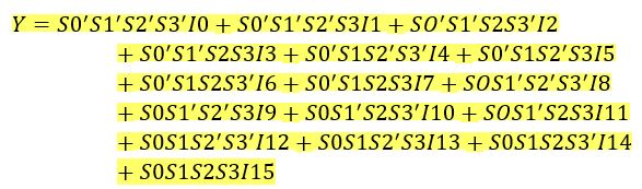
The logic circuit of the above expression is;
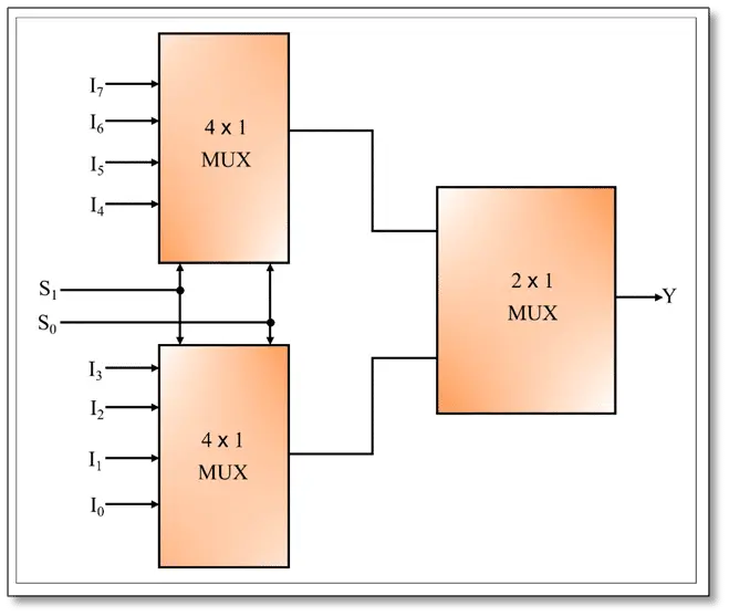
We can also implement higher-order multiplexers using lower-order multiplexers. The realization of an 8×1 MUX using 4×1 MUX and 2×1 MUX, and a 16×1 MUX using 8×1 MUX and 2×1 MUX is given below.
8×1 MUX using 4×1 MUX and 2×1 MUX
The realization of an 8×1 multiplexer using two 4×1 multiplexers and one 2×1 multiplexer is shown in the following figure.
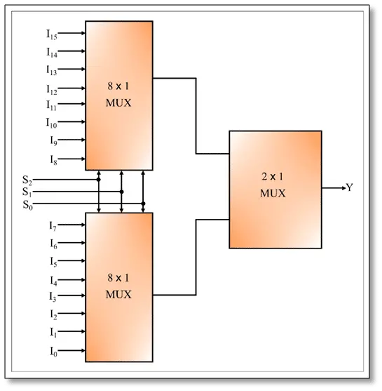
16×1 Multiplexer using 8×1 MUX and 2×1 MUX
The realization of a 16×1 MUX using two 8×1 multiplexers and one 2×1 multiplexer is shown in the following figure.
Applications of Multiplexers
Multiplexer is a widely used combinational logic circuit used in a variety of digital electronic circuits. Some key applications of multiplexers are listed below:
- Multiplexers are used in digital communication systems for data transmission.
- It is used for data selection and routing applications for the transmission of multiple signals over a single communication channel.
- Multiplexers also find applications in control systems and signal processing to select and process signals from different input lines.
- In microprocessors and microcontrollers, multiplexers are used for address decoding.
- Mux is Used in digital systems to provide bus arbitration so that multiple devices can share a common bus.
- Used in digital data processing for the detection and correction of errors