This article describes the Architecture of 8051 Microcontroller. A microcontroller is a programmable integrated circuit (IC) that contains a small CPU, RAM, and I/O pins.
The 8051 microcontroller was developed by Intel Corporation in 1981. Initially, it was built using NMOS technology. But the NMOS technology needs more power. So, later Intel introduced a new version of the 8051 microcontrollers based on CMOS technology. They Draw the Architecture of 8051 Microcontroller which is called 8051.
The 8051 microcontroller is an 8-bit microcontroller. The 8051 microcontroller has an 8-bit processor which means, it can operate on 8-bit data at a time. It is the most commonly used microcontroller. The 8051 microcontroller is available in 40-pin DIP (Dual Inline Package), 128 bytes RAM, 4 kb ROM, and two 16-bit timers. The 8051 microcontroller has four parallel 8-bit ports which are programmable and addressable based on requirements. The on-chip crystal oscillator frequency is 12 MHz and is integrated into it. Microcontroller 8051 has a 16-bit address bus and an 8-bit data bus.
Microcontrollers are used in applications where programming is to be performed on the smallest space present. A microcontroller holds a separate memory location for both data and programs.
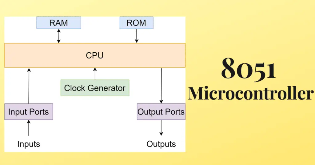
Internal Architecture of 8051 Microcontroller
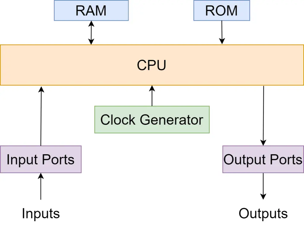
Each unit in the Internal Architecture of 8051 Microcontroller is embedded in the chip to execute a specific operation. now, we will discuss the elements of the Architecture of the 8051 Microcontroller.
1. Central Processing Unit (CPU)
The 8051 microcontroller uses an 8-bit processor. It is the most important part of the 8051 microcontroller architecture. This unit will carry out operations on the 8-bit data. CPU is the heart of the microcontroller. The execution of the programs gets stored in the memory and is performed by the processor. The ALU performs arithmetic and logical operations on the 8-bit data. The ALU, internal registers, and program counters are contained inside the CPU. 8051 microcontroller has a processor that possesses a special feature by which single-bit or 8-bit data can be processed. It means ALU has the ability to access every single bit of data either to clear, set, or move for any logical computation.
2. Memory
The 8051 microcontroller has on-chip program memory, that is, ROM, and on-chip data memory, which is, RAM.
2a. ROM
8051 microcontroller contains 4 kb ROM. ROM has an addressable space from 0000H to 0FFFH. ROM is also called a program/code memory. Hence, ROM is used only by the programmer to store programs that must be executed by the microcontroller. The operations which are executed by the device in which the microcontroller is present would be stored in the ROM of the memory during the time of fabrication. So, ROM cannot be changed or modified.
2b. RAM
RAM is also called data memory.8051 microcontroller contains 128 bytes of RAM. RAM stores data or operates for small time duration. RAM may be altered at any time depending on the need of the user. RAM is also called data memory because RAM stores the data temporarily. From the 128 bytes, the first 32 bytes are held by working registers. These are 4 banks that separately have 8 registers. These registers can be accessed by their name or address. At a particular time, a single register bank can only be used. In applications where larger memory space is needed, external RAM, and ROM/EPROM can be used.
3. Input/Output Port
The 8051 microcontroller has 4 parallel ports. Each port has 8 bits each and hence provides 32 input-output pins. All 4 ports work bidirectionally, this means, either input or output can be exchanged according to the software control.
4. Timer and Control Unit
The timers help create a time gap or delay between 2 events. The 8051 microcontroller has 2 timers. Both are 16-bit each. So, they can produce two delays simultaneously in order to generate an appropriate delay. The microcontroller has a hardware delay in which a physical device is used by the processor for producing the required delay. This physical device is called a timer. It produces delays according to the demand of the processor. After the delay is over, it sends a signal to the processor. The processor is not used to produce delay because then the processor will be busy and will not perform any other function during the delay time duration. So, when a timer is present in the microcontroller, the processor is free to execute other operations.
5. Interrupts
An interrupt is a subroutine call that temporarily suspends the microcontroller’s main program. Interrupt helps the microcontroller to perform some other program that is more important than the main program at a particular time. After this is executed, it again resumes execution of the main program. They provide a method to postpone the current process and carry out a sub-routine and later again restart the standard program. The 8051 microcontroller has 5 interrupt sources, from which two are peripheral interrupts, two are timer interrupts and one is a serial port interrupt.
Types of interrupts
The different types of interrupts are:
- TF0 (Timer 0 Overflow Interrupt)
- TF1 (Timer 1 Overflow Interrupt)
- INT0(External Hardware Interrupt)
- INT1(External Hardware Interrupt)
- RI/TI(Serial Communication Interrupt)
6. Bus
A bus is a group of wires that function as a communication canal or a means of transferring data. These buses may consist of 8, 16, or more cables. So, a bus can carry 8 bits, and 16 bits together. There are two types of buses:
6a. Address bus
8051 microcontroller has a 16-bit address bus. It is used for addressing memory positions. It can be utilized for transmitting the address from the CPU to memory.
6b. Data bus
8051 microcontroller has an 8-bit data bus. It is used to carry data.
7. Oscillator
The 8051 microcontroller has an on-chip oscillator that acts as a time source or CPU. The oscillator frequency is 12MHz.
8. Registers
Registers are mainly used to store data and short-term instruction. The short-term instructions are mainly used to process addresses to fetch data. The 8051 microcontroller has 8-bit registers, starting from D0 to D7. D0 is the least significant bit or say LSB and D7 is the most significant bit or say MSB. Registers are of two types: General purpose type and special purpose type. Some general-purpose registers are listed below:
Accumulator: Accumulator is mainly used for executing arithmetic and logic instructions.
Registers like B, R0 to R7: They are used for storing instruction addresses and data.
Data Pointers or DPTR: They are used for allowing and processing data in dissimilar addressing modes. It has DPH (high byte) and DLP (low byte) to hold a 16-bit address. It may be used as a base register within not direct jumps, lookup table instructions, and external data transfer.
Program Counter (PC): PC is a 16-bit register that stores the next instruction’s address.
All registers are 8-bit registers except the program counter and data pointer registers.
In the register bank R0 to R7 shows the location of RAM, that is, zero location and seventh location. The second bank register will begin from location 8 and end at 05H. For the third bank, the register would start from 10H and end at the 17H location. The final bank can be placed from 18H to 1FH.
9. Data Types
The 8051 microcontroller has simply one 8-bit data type where the size of each register is 8 bits. For data bigger than 8 bits, the programmer needs to separate data into 8 bits before processing it. In assemblers, the most used data directive is the DB directive in assembly language.
10. PSW Register
The program status word (PSW) is a type of register in the microcontroller. It is also known as a flag register. It is used to depict the position of arithmetic logic instructions such as zero, carry bit, etc. It is an 8-bit register where 6-bits are used. This register includes 8 flags. These flags are known as conditional flags. They perform instructions simply when the condition is satisfied. The conditional flags are:
- Overflow
- Parity
- Auxiliary carry
- Carry
The bit numbers 3 and 4 of the PSW register are used to alter the bank registers and bit numbers like 1 and 5 are not used but they may be used by the programmer for the execution of a specific task.
11. Stack
A part of RAM, that is, a stack is mainly used by the processor for storing data or addresses temporarily. In the 8051 microcontrollers, the stack is 8-bit and can hold data from 00-FFH. Once the stack pointer is activated, it includes the 07 value.
12. Addressing modes
The data in a microcontroller is stored within the memory. A register can be used to get instant value. This can be done in different ways, which are known as addressing modes. The different addressing modes depend on the plan of the manufacturers. The addressing modes of the 8051 microcontroller are:
- Register
- Register Indirect
- Immediate
- Indexed
- Direct
This is all about the 8051 microcontroller architecture.
Applications of Architecture of Microcontroller 8051
Some of the applications of the Architecture of Microcontroller 8051 are:
- Consumer appliances: Microcontrollers are used in appliances like TV tuners, remote controls, Sewing machines, etc.
- Home Appliances: Microcontrollers are used in home appliances like TVs, VCRs, Home Security Systems, Musical Instruments, etc.
- Communication Systems: Microcontrollers are used in communication systems like mobile phones, Intercoms, Paging devices, Answering machines, etc.
- Office: Microcontrollers are used in offices like Fax machines, Laser printers, Copiers, etc.
- Aeronautical and Space
- Medical equipment
- Defense systems
- Robotics
- Radio and networking equipment