In this article, we will discuss the Logic AND Gate, its definition, symbol, Boolean function, truth table, etc. So, let’s get started with the basic introduction of logic AND gate.
What is a Logic AND Gate?
In digital electronics, an AND gate is a type of basic logic gate used for implementing logical multiplication.
The logic AND gate is one whose output is high or logic 1 only when all its inputs are high or logic 1, and its output is low or logic 0 when any of its inputs are at a low level or logic 0. The AND operation is specified by the dot (.) symbol.
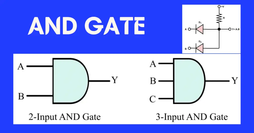
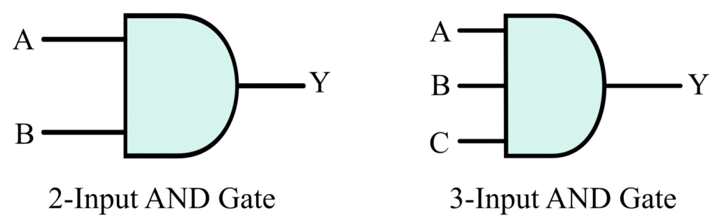
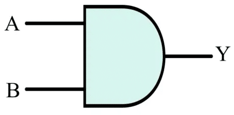
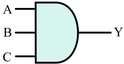
The logic circuit symbols of a two-input AND gate and a three-input AND gate are shown in the following figure.
Boolean Expression
The Boolean expression of a two-input AND gate is given below:
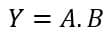
Where A and B are the input variables, and Y is the output variable.
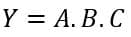
The Boolean expression of a three-input AND gate is given below:
Operation of AND Gate
The operation of a two-input AND gate for different input combinations is explained in the following bullet points:
- When A = 0 and B = 0, the output Y = 0.
- When A = 0 and B = 1, the output Y = 0.
- When A = 1 and B = 0, the output Y = 0.
- When A = 1 and B = 1, the output Y = 1.
The operation of a three-input AND gate for different possible input combinations is described below:
- When A = 0, B = 0, and C = 0, the output Y = 0.
- When A = 0, B = 0, and C = 1, the output Y = 0.
- When A = 0, B = 1, and C = 0, the output Y = 0.
- When A = 0, B = 1, and C = 1, the output Y = 0.
- When A = 1, B = 0, and C = 0, the output Y = 0.
- When A = 1, B = 0, and C = 1, the output Y = 0.
- When A = 1, B = 1, and C = 0, the output Y = 0.
- When A = 1, B = 1, and C = 1, the output Y = 1.
From the above discussion, it is clear that the output of an AND gate is high or logic 1 only when all of its inputs are high or logic 1. For all other input combinations, the output is low or logic 0.
Truth Table of AND Gate
2 Input AND Gate
The truth table of a two input AND gate is given below:
 Input | Output | |
| A | B | Y = A.B |
| 0 | 0 | 0 |
| 1 | 1 | 0 |
| 1 | 0 | 0 |
| 1 | 1 | 1 |
3 Input AND Gate
The following is the truth table of a three-input AND gate:
 Inputs | Output | ||
| A | B | C | Y = A.B.C |
| 0 | 0 | 0 | 0 |
| 0 | 0 | 1 | 0 |
| 0 | 1 | 0 | 0 |
| 0 | 1 | 1 | 0 |
| 1 | 0 | 0 | 0 |
| 1 | 0 | 1 | 0 |
| 1 | 1 | 0 | 0 |
| 1 | 1 | 1 | 1 |
Multi-Input AND Gate
An AND gate can have any number of inputs, but the most widely used AND gates in digital electronics are two-input and three-input AND gates.
However, we can implement AND gate for any number of inputs by suitably connecting multiple two-input AND gates as shown in the following figure.
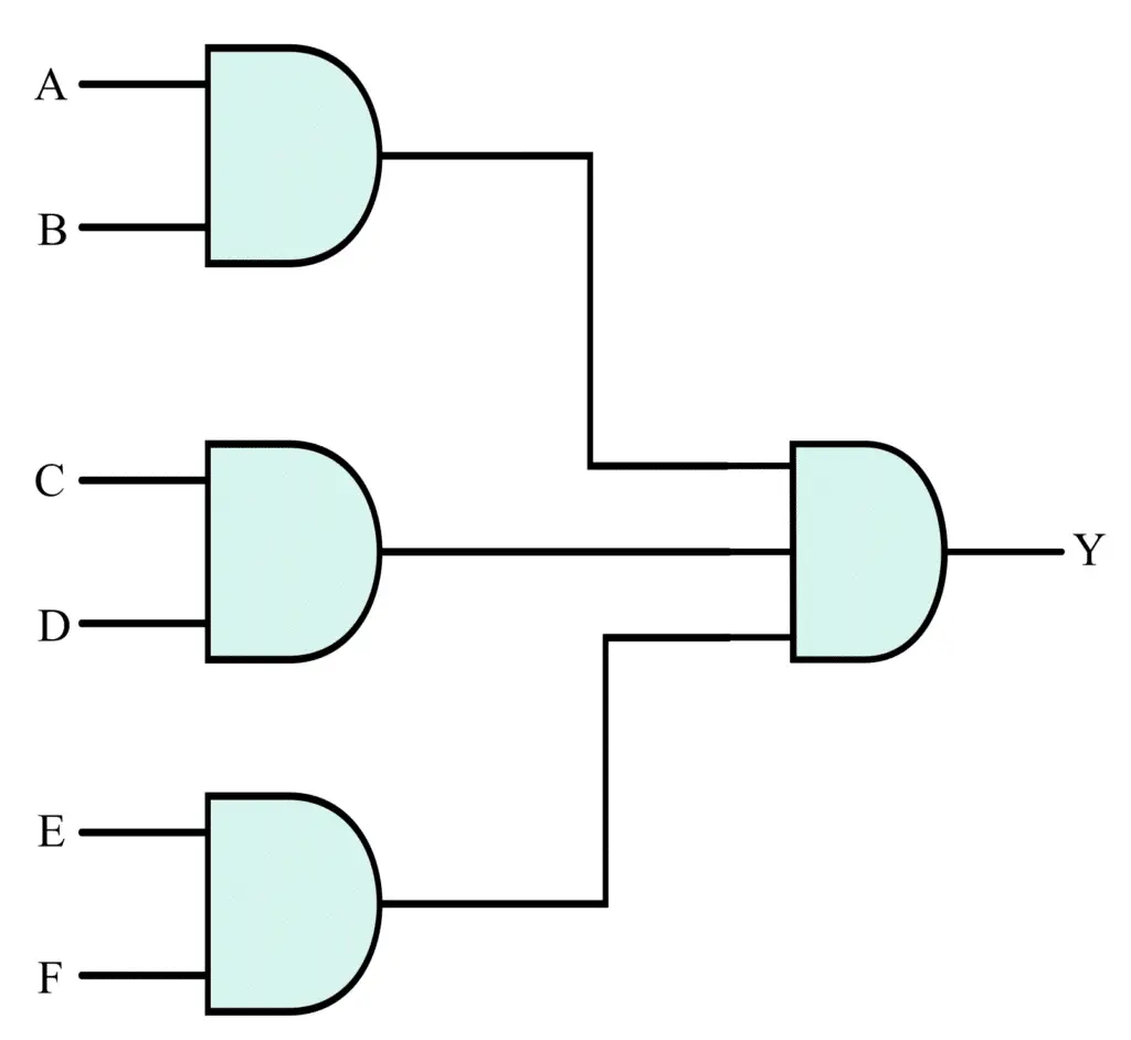
Here, we have realized a six-input AND using three two-input AND gates and a three-input AND gate.
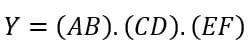
The Boolean expression for the output of this AND gate is given by,
AND Gate Circuit Diagram
We can form AND gate circuits using diodes or transistors.
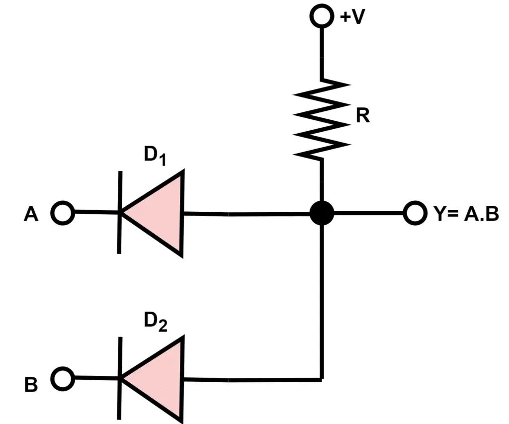
AND Gate Diode Circuit Diagram
The AND gate can be formed using two diodes. The circuit diagram of the diode AND gate circuit is given below.
If any of the diodes conduct, then the voltage drop across the diode is 0.6 volts and the output of the diode AND gate is LOW. Let us understand with an example
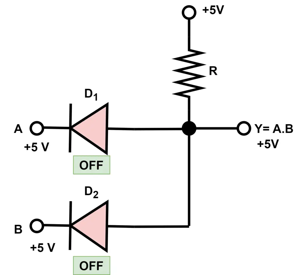
If A=1 and B=1, then both diodes are in the reverse bias state then the output will be HIGH. + V volts will appear at the output and we will get High at the output.
If A=0 and B=0, then both diodes are in the forward bias state then the output will be equal to the foreword voltage drop of the diode. you will get 0.6 volts at the output.
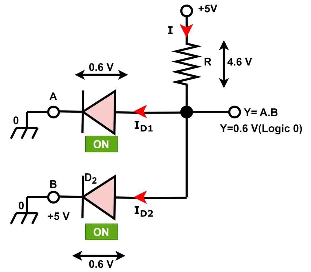
If any of the inputs is 0( Low), then output will be 0(LOW)
AND Gate Transistor Circuit Diagram
We can construct a logic AND gate in RTL (Resistor-Transistor Logic). A typical two-input logic AND gate in RTL logic is shown in the following figure.
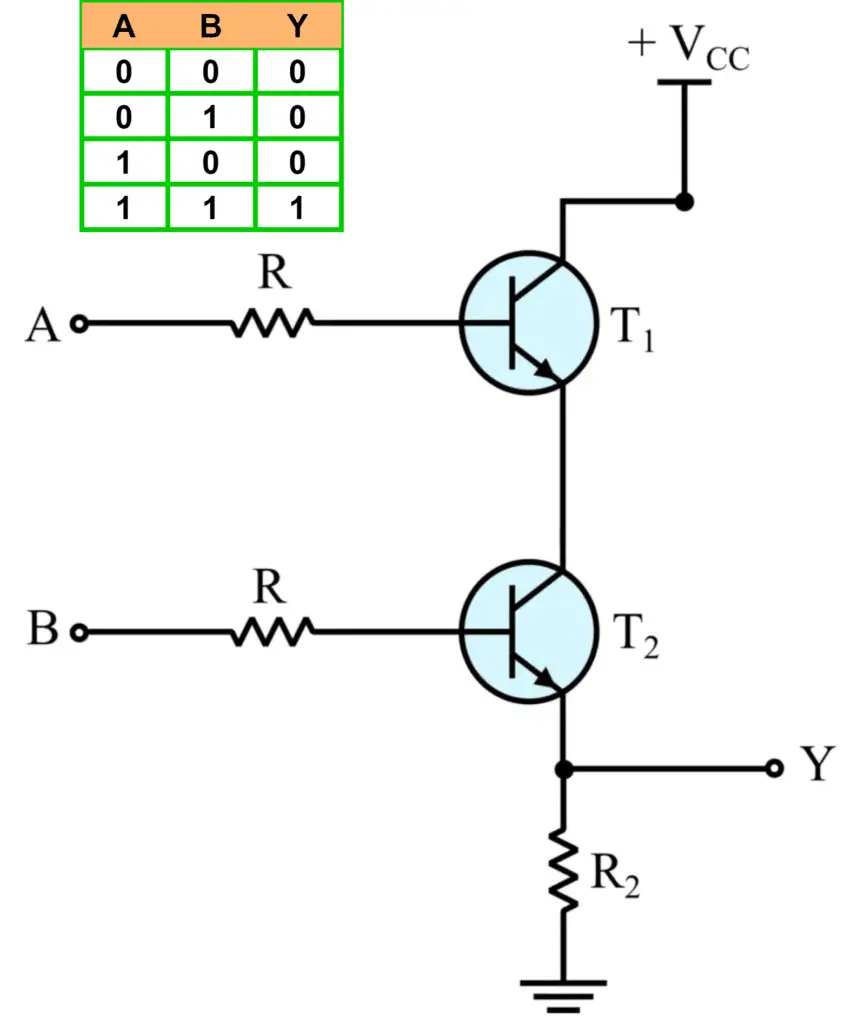
In the above circuit, we will get output voltage across R2 resistance if the emitter current flows through transistor T2. It is only possible when both transistors T1 and T2 conduct. Both transistors will conduct if the bases of these transistors get logic 1( High). If A=B=1, the base current will flow through T1 and T2 transistors, causing transistors to conduct and we get logic 1( High) at the output.
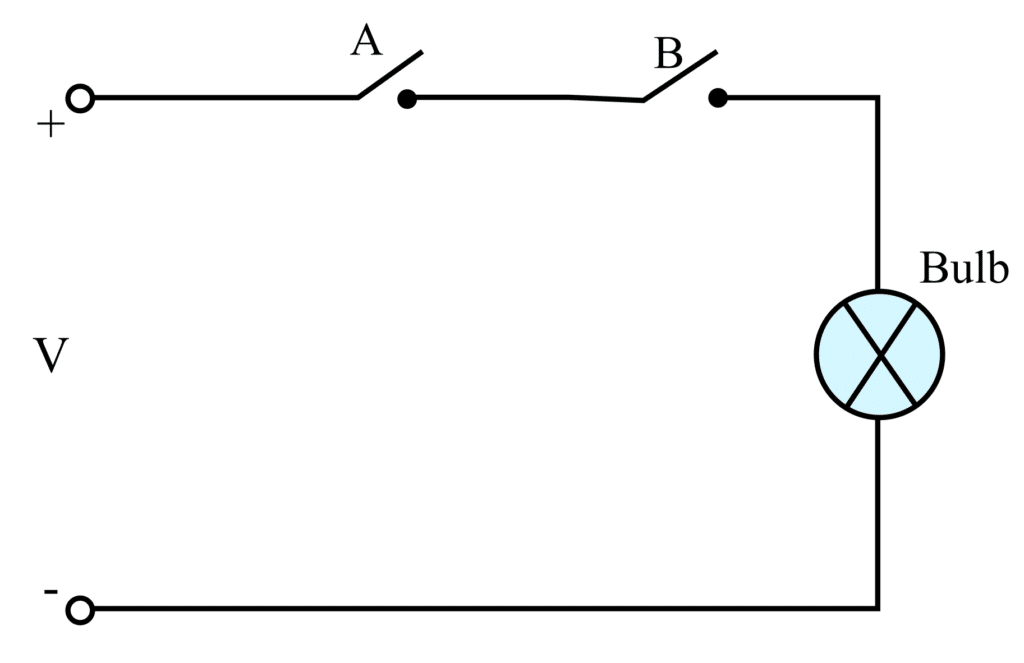
Equivalent Electrical Circuit of AND Gate
The equivalent electrical circuit of AND gate using switches and lamps analogy is shown in the following figure.
AND Gate Integrated Circuits
The commonly available AND gate integrated circuits are as follows:
| Logic Category | AND Gate IC |
| TTL Logic | 74LS08 (Quad two-input) |
| TTL Logic | 74LS11 (Triple three-input) |
| TTL Logic | 74LS21 (Dual four-input) |
| CMOS Logic | CD4081 (Quad two-input) |
| CMOS Logic | CD4073 (Triple three-input) |
| CMOS Logic | CD4082 (Dual four-input) |
Hence, this is all about Logic AND Gate, its definition, circuit symbol, truth table, Boolean expression, etc.