In this article, we shall discuss about unijunction transistor (UJT), its definition, construction, circuit symbol, working, and applications.
What is UJT?
UJT stands for Unijunction Transistor. The unijunction transistor, or UJT, is a three-terminal semiconductor device that has only one PN-junction. The unijunction transistor is widely used in several electronic circuits like free-running oscillator circuits, synchronized oscillator circuits, and low to moderate-frequency pulse generators.
The unijunction transistor was accidentally invented in research on germanium tetrode transistors at General Electric and was patented in 1953.
Construction of UJT
The unijunction transistor consists of three terminals, namely emitter (E) and two bases (B1 and B2). Since it has two bases and one PN junction, hence it is sometimes also called a double-base diode.
The base of the UJT is made up of a lightly doped n-type semiconductor (usually silicon), and two metallic contacts are attached to its ends and are designated as B1 and B2. The emitter is made up of a heavily doped p-type semiconductor. These two semiconductors give a single PN-junction in the device.
In a practical UJT, the emitter is fabricated closer to the base B2 than B1, which makes the unijunction transistor an unsymmetrical device. There is a resistance between the two bases, B1 and B2, with the emitter open-circuited. This resistance is known as Interbase resistance.
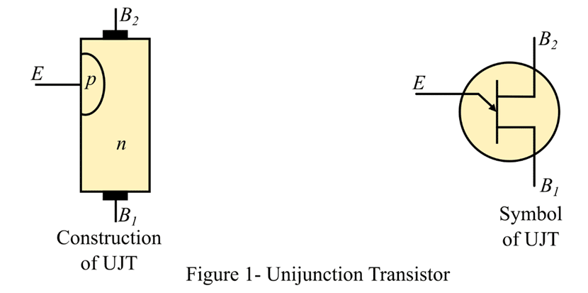
Figure 1 shows the schematic diagram and circuit symbol for a unijunction transistor. In the circuit symbol, the emitter lead is shown with an arrow, which shows the direction of conventional current when the emitter-base junction is conducting an electric current. A UJT is a current-controlled negative resistance device.
Equivalent Circuit of UJT
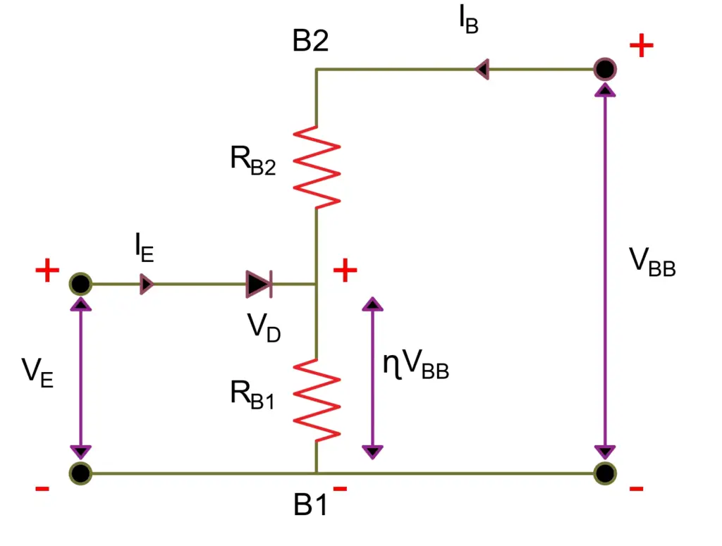
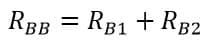
- The resistance of the silicon bar is known as the inter-base resistance. Its value varies from 4 kΩ to 10 kΩ.
- The resistance RB1 is the resistance of the material between the emitter and B1 region. The value RB1 is variable, and it depends upon the bias voltage across the PN junction.
- The resistance RB2 is the resistance of the material between the emitter and the B2 region.
- The emitter pn-junction represents a diode.
- When no voltage is applied to the UJT, the value of inter-base resistance is given by
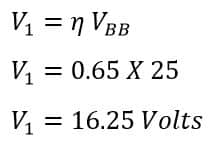
The voltage across RB1 is V1
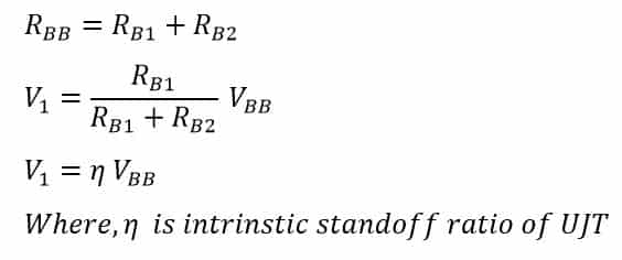
The intrinsic stand-off ratio of UJT is;
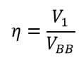
The value of the intrinsic standoff ratio of UJT (ƞ )generally lies between 0.51 and 0.82.
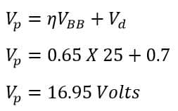
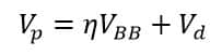
The Peak Point Voltage (VP) of the UJT
Operation of UJT
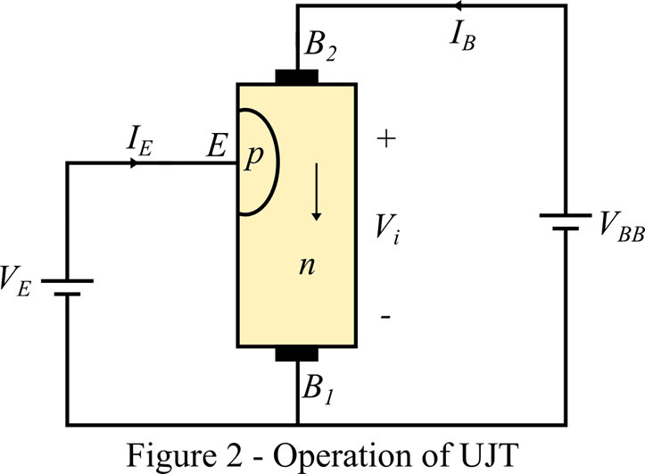
When a positive voltage is applied at the emitter, as shown in Figure 2, the PN-junction remains reverse-biased till the input voltage is less than the internal voltage (Vi). When the applied voltage becomes greater than Vi, the PN-junction becomes forward-biased. Thus, the holes started to move from the positive terminal (B2) to the negative terminal (B1).
The accumulation of holes in the emitter to B1 region decreases the resistance of the n-type semiconductor bar. Consequently, the internal voltage drop from the emitter to B1 is decreased, and hence, the emitter current IE is increased. With the accumulation of a large number of holes, a condition of saturation will eventually be reached. In this condition, the emitter current is limited by the emitter power supply and the unijunction transistor is now said to be in the ON state.
Types of Unijunction Transistors
There are three main types of unijunction transistors, which are described below.
- Original UJT – The original unijunction transistor is simply a bar of n-type semiconductor with a p-type semiconductor diffused into it somewhere along the length of the bar.
- Complementary UJT – The complementary unijunction transistor is a bar of p-type semiconductor material with an n-type semiconductor diffused into it somewhere along its length.
- Programmable UJT – The programmable unijunction transistor is a device that has multiple junctions and two external resistors. The programmable unijunction transistor is not directly interchangeable with the conventional UJT but can perform a similar function.
Characteristics Curve of UJT
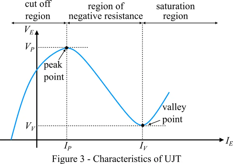
The characteristics curve of the unijunction transistor is shown in Figure 3. We can explain the characteristics of a unijunction transistor by the following three parameters-
- Cut-off Region
- Negative Resistance Region
- Saturation Region
1. Cut-off Region
The part of the characteristics curve where the unijunction transistor does not get sufficient voltage to turn on is called the cut-off region. In this region, the unijunction transistor remains off-state.
2. Negative Resistance Region
In the negative resistance region, the unijunction transistor(UJT) receives enough voltage to turn on. In this region, when we increase the voltage applied to the emitter terminal, it attains its peak value (VP) after a certain time. After this point, the voltage drop across the device starts decreasing, and this reduction stops at a voltage VV point, which is called the valley point. However, the current through the device is still increasing. Therefore, the resistance of the unijunction transistor is found to be negative in this region, so it is called the negative resistance region.
3. Saturation Region
The saturation region is the area on the characteristics curve of the unijunction transistor in which the voltage and current increase if the emitter voltage is increased.
Advantages of UJT
- It is a low-cost device.
- Excellent characteristics
- It draws low power under normal operating conditions
Applications of UJT
The unijunction transistor (UJT) is used in the following applications-
- It is used as a relaxation oscillator.
- It is used as a voltage regulator.
- It is used for the generation of sawtooth waveforms.
- It is most widely used as a triggering device for SCRs.
- It may also be used as a phase control circuit, etc.
Solved Problem
A UJT has an intrinsic stand-off ratio of 0.65. The voltage applied between the base B1 and B2 of UJT is 25 volts. The forward voltage drop in the PN-junction is 0.7 V. Find.
- Value of stand-off voltage
- Peak-point voltage
Stand-off voltage
Peak-point voltage