Core saturation in a transformer happens when the transformer’s magnetic core can not no longer carry the magnetic flux. The transformer core can not carry the flux above its rated capacity. In this article, we will discuss why core saturation happens and what its adverse effects on transformers are.
What is Core Saturation?
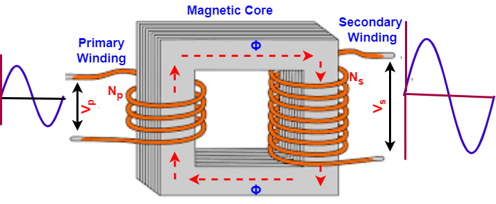
You are all aware that the transformer’s core is made of magnetic materials that carry more flux than the air core, and using a magnetic core, it is possible to construct transformers in smaller sizes. When the primary winding receives the AC supply, it generates the flux. This flux flows through the magnetic core and finally links to the secondary winding, producing a voltage in the secondary.
The primary function of the magnetic core is to carry the magnetic flux. The maximum amount of magnetic flux that a magnetic core can carry is called the rated flux density of the core. The rated flux density of the core is expressed in Tesla or Weber/m2.
The transformer core is typically made of ferromagnetic materials, which can carry the flux up to their rated capacity. The ferromagnetic materials can not carry the magnetic flux above their rated capacity and fail to carry excess magnetic flux. It means if we increase the MMF( ampere-turns) in the primary winding to increase the flux., the core may not be capable of carrying that increased flux. The inability of the core to carry magnetic flux above the rated flux capacity is called core saturation.
For example, a transformer core can carry a magnetic field of 1.7 Tesla, and if we generate 1.9 Tesla flux density in the transformer primary, then the transformer core can not carry this increased flux, and the transformer is said to be a saturated transformer.
Reasons for Core Saturation in Transformer?
The reasons for core saturation are excessive voltage, lower frequency, and DC offset current. We will discuss all these in detail in the subsequent texts.
The core saturation in the transformer happens because of the excessive flux that a core can not handle. Therefore, let us first understand the factors that affect the flux in the transformer.
The primary winding of the transformer is made up of the coils. The coil has a number of turns in it. The general arrangement of the transformer winding and core is shown in the image below.
When we apply AC voltage to the primary, EMF is induced in it.
Let,
EP= Voltage induced in the primary
f= Frequency of supply source
Np= Number of Turns in Primary
Φ= Magnetic flux
The voltage induced in the primary can be given as;
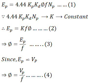
It is evident from the above equation that the flux in the transformer core is directly proportional to the applied voltage and frequency.
1. Excessive Voltage
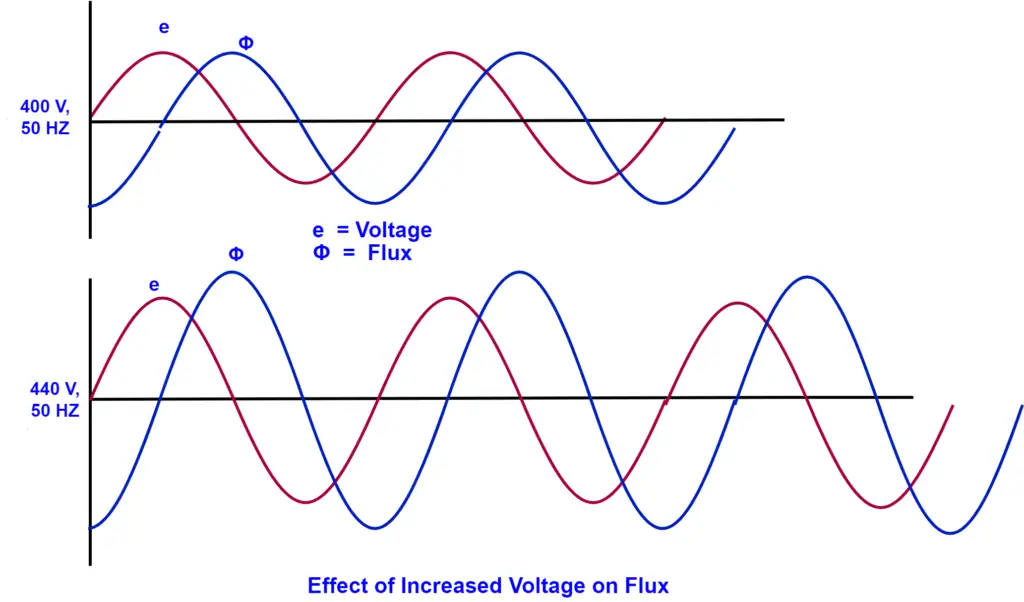
The flux in the core is proportional to the voltage, and if the voltage increases alone without changing the frequency, the core flux increases above the rated flux. When the primary winding of a transformer is subjected to excessive voltage, the core flux can reach saturation during the peak moments of the AC waveform. When a transformer rated at 440 volts and 50 Hz is operated at 440 volts and 50 Hz, the flux increases by approximately 10%. The effect of increased voltage on core flux is shown in the image below.
It is important to note that the flux gets distorted when the transformer core is saturated, which means the flux linking to the secondary winding cannot produce a sinusoidal voltage. The distorted waveform in the secondary winding produces harmonics that can cause problems in the electrical network.
Read More: Effects of Harmonics on Transformer
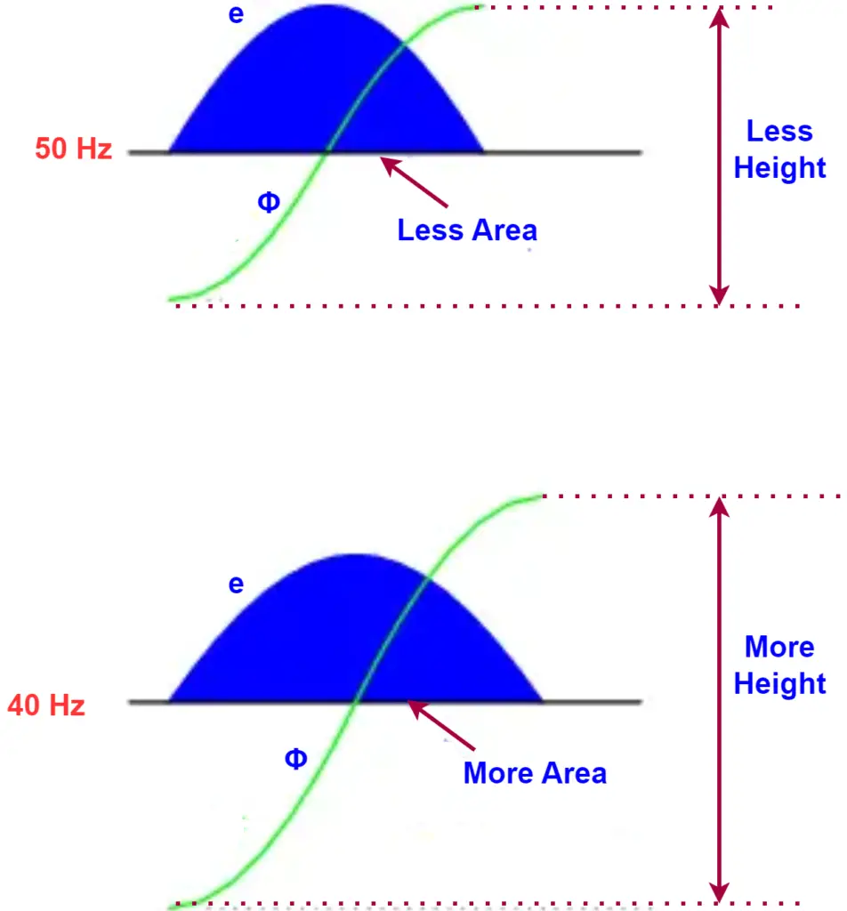
2. Lower Frequency
Equation 4 clearly shows that the flux in a transformer core varies inversely with the frequency. When the frequency drops below the rated value, the flux in the core increases; for example, if a transformer rated to operate at 50 Hz is used at 40 Hz while maintaining the same voltage rating, the core flux will increase, resulting in core saturation.
The significance of reducing frequency can be observed in the figure depicted below.
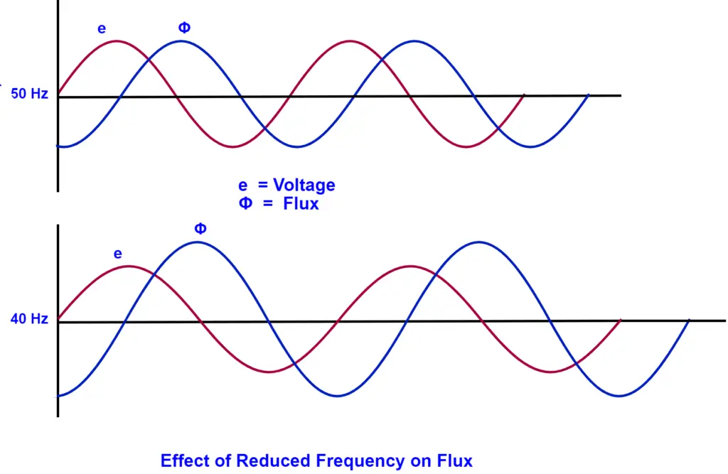
It’s a fact that the integral of any mathematical function is directly proportional to the area accumulated underneath the curve of that function. In the case of electrical engineering, where we deal with waveforms, this concept holds true as well.
When we compare the 40 Hz waveform to the 50 Hz waveform, we can see that each half-cycle of the 40 Hz waveform accumulates more area between it and the zero line of the graph than the 50 Hz waveform. This means that the flux, which is the integral of the voltage, will attain higher values in the case of 40 Hz as compared to 50 Hz, as shown in the below figure.
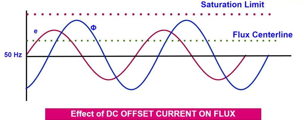
3. DC Offset Current
The fault current in the electrical network has a symmetrical AC component and DC offset current. In a fault condition, the core flux is the summation of flux produced due to AC and DC components. In normal conditions, only the AC component produces the magnetic flux.
The additional flux produced by the DC offset current causes the core flux waveform to push closer to the saturation point.
Effects of Core Saturation in Transformer
Core saturation in the transformer causes increased thermal stress on the transformer. The excitation current increases exponentially after 110 % nominal voltage is applied. The increased excitation current causes overheating of the core and can cause permanent damage.
The excess flux that the core can not carry gets leaked and links to the other parts of the structural parts, causing eddy current heating.
The saturated transformer produces harmonics in the electrical system that cause increased copper loss in the electrical network. The saturated transformer produces 5th-order harmonics, which may cause the differential protection relay to operate and cause nuisance tripping. The differential relay has a 5th harmonic restraint function in it to prevent the transformer from such nuisance tripping.
Final Words
When the volts to Hertz ratio (V/f) ratio changes from the rated V/f ratio, core saturation occurs in the transformer, leading to excessive heating and distortion of the sinusoidal voltage. It is essential to maintain the rated V/f ratio to avoid such issues.