Phasor diagrams are a graphical way of representing relationships between different alternating quantities in an AC circuit. In electrical engineering, phasor diagrams and phasor algebra are two crucial concepts while dealing with alternating current circuits and quantities. Phasor algebra is a mathematics that provides sets of rules and operations to perform operations like addition, subtraction, etc. on phasor quantities.
In this article, we will discuss various concepts of phasor diagrams and phasor algebra. Here, we will cover the basic definition and significance of phasor diagrams and phasor algebra in electrical engineering and AC circuits.
What is a Phasor Diagram?
A phasor diagram is simply a graphical representation of alternating electrical quantities. It is also called a vector diagram. Where a vector or phasor is a mathematical tool used to represent alternating electrical quantities.
A vector or phasor is basically a complex number having two parts namely, real part and imaginary part. Each phasor has two components i.e., magnitude and phase angle.
The mathematical diagram which represents the magnitude and phase angle of electrical quantities is termed a phasor diagram.
In a phasor diagram, the magnitude represents the maximum or RMS value of an alternating electrical quantity and the phase angle represents the angular position of the quantities with respect to the reference axis.
The length of a phasor in a phasor diagram represents the magnitude of the quantity and the angular displacement of the phasor with respect to the reference axis represents the phase angle of the quantity.
Phasor diagrams make the process of analyzing AC circuit simpler and also reduces the time required for calculations.
What is Phase Difference?
The difference or angular displacement between the phase angles of two or more electrical quantities is called phase difference.
For example, consider a waveform showing two sinusoidal alternating voltages V1 and V2.
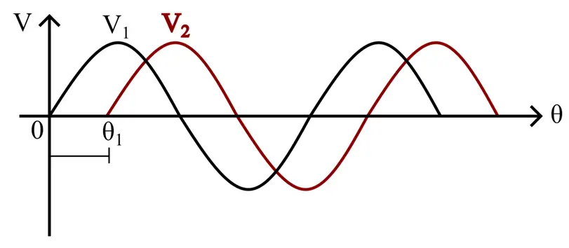
In this waveform diagram, the voltage V1 starts from zero, and the voltage V2 starts after some time, let’s say at an angle, of θ1. Therefore, there is a difference between the angular positions of the two voltages, this is called the phase difference.
Mathematically, the phasor difference is given by,
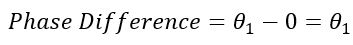
Phasor Diagram of Sinusoidal Waveform
We can also draw the phasor diagram of the above-shown sinusoidal waveform. For this, firstly we draw a reference axis, then draw the phasor of different quantities of the waveform.
For the above-shown waveform, the phasor diagram is shown in the following figure.
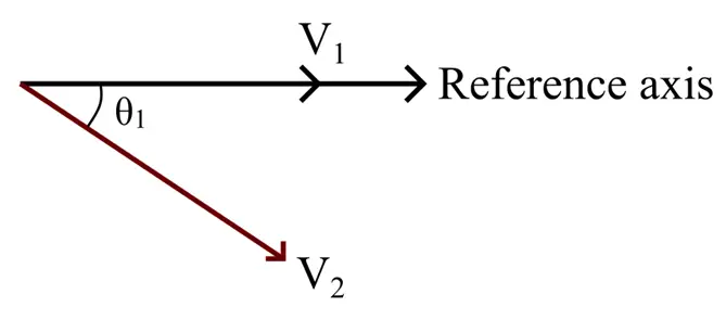
Here, we have taken the voltage V1 along the reference axis as the phase angle of the voltage wave V1 is 0 as it starts at zero.
The second voltage wave V2 starts at an angle θ1 after wave V1. Hence, there is a delay of an angle θ1 between the voltages V1 and V2. Since, the voltage V2 is lagging behind the voltage V1 by the angle θ1, hence in the phasor diagram is represented as a phasor lagging behind the voltage V1 by the angle θ1.
This way we can draw the phasor diagram of sinusoidal electrical quantities.
From this phasor diagram, we can also state the relative angular relation between the voltages V1 and V2 as follows:
- The voltage V1 is ahead of the voltage V2, hence it can be stated as the voltage V1 is leading the voltage V2.
- In another way, voltage V2 is behind voltage V1, hence it can be stated as voltage V2 is lagging voltage V1.
This concept of lagging and leading is quite important while performing phasor operations.
What is Phasor Algebra?
Mathematics that provides a set of rules and operations to manipulate phasors and phasor quantities is termed phasor algebra.
Phasor algebra allows us to perform various arithmetic operations like addition, subtraction, multiplication, division, etc. on phasor quantities. Hence, it helps to solve complex AC circuits easily.
In simple terms, phasor algebra is a mathematics that converts complex ac circuit problems into simple algebraic equations.
Now, let us discuss some basic operations of phasor algebra.
(1). Addition of Phasors:
We can use the rectangular form of phasors to add them. In the phasor addition, the real parts of the two phasors are added together and the imaginary parts are added together.
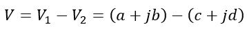
For example, consider two voltage phasors given by,
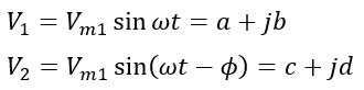
Here, a and b are the real and imaginary components of the voltage phasor V1, and c and d are the real and imaginary components of the voltage phasor V2.
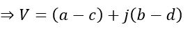
Therefore, the resultant phasor voltage of these two voltages is
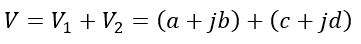
Rearranging the real and imaginary components, we get,
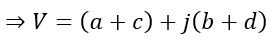
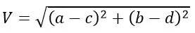
The magnitude of this resultant voltage phasor V is given by,
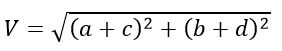
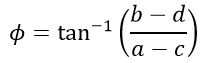
And the phase angle is given by,
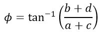
For example, consider two voltages V1 = 50 V and V2 = 100 V respectively, where the voltage phasor V1 is leading the V2 by angle, φ = 300.
The phasor diagram of the above example is given below.
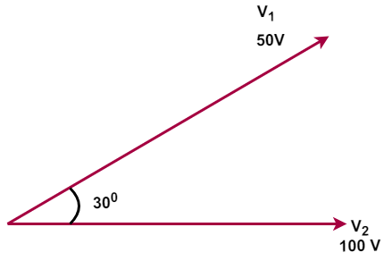
Voltage V2 is on the reference axis,
Horizontal component =V2 cos 0o = 100 V
Vertical Component = V2 sin 0o = 0
Thus, voltage V2 can be represented as – 100+J0
Voltage V1 is lagging the voltage V2 by 30o
Horizontal component= V1 cos 30o = 50 X 0.866= 43.3 V
Vertical Component = V1 sin 30o =50 X 0.5= 25V
Thus, voltage V2 can be represented as, 43.3+J25
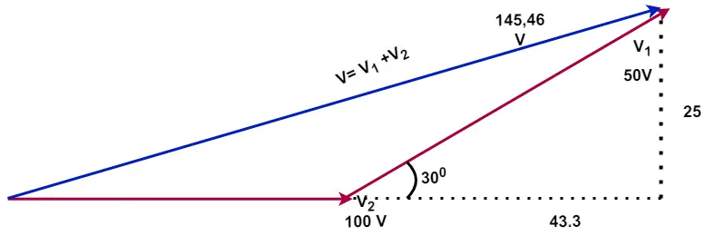
The addition of these two vectors
V=(100+J0)+( 43.3+J25)
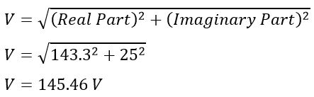
V=143.3 +j25
Resultant voltage V,
The resultant voltage phasor diagram is shown below.
(2). Subtraction of Phasor:
Similar to phasor addition, the subtraction of phasors is performed using their rectangular form for ease.
The subtraction of the above voltage phasors V1 and V2 is obtained as follows,
Rearranging the real and imaginary components, we get,
The magnitude of this resultant voltage phasor V is given by,
And the phase angle is given by,
(3). Multiplication of Phasors:
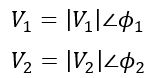
The multiplication of phasors can be performed using their polar form. For example, consider two voltages V1 and V2, and their phase angles ϕ1 and ϕ2 respectively.
In polar form, they are represented as,
Then, their multiplication will be performed as follows
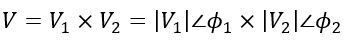
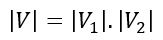
The magnitude of the resultant voltage phasor is
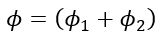
The phase angle of the resultant voltage phasor is
4). Division of Phasors:
Similar to multiplication, the division of phasors is easier in the polar form. The division of the above voltage phasors V1 and V2 is performed as follows,
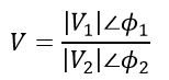
The magnitude of the resultant phasor is
The phase angle of the resultant phasor is
Now, let us discuss the phasor diagram of a balanced three-phase system.
Phasor Diagram of 3-Phase System
In a balanced three-phase electrical system, the magnitudes of three-phase voltages are equal and the three voltages are displaced from each other by an angle of 120° electrical.
The phasor representation of a balanced three-phase system is shown in the following figure.
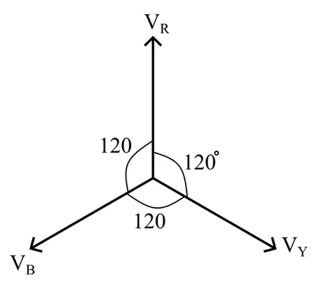
From the phasor diagram, it is clear that the voltage VR, VY, and VB are equal in magnitude (equal length of phasors) and they are equally displaced from each other by an angle of 120° electrical.
Conclusion
Hence, this is all about phasor diagrams and phasor algebra in electrical engineering. The phasor diagram and phasor algebra are the crucial concepts used to analyze ac electrical circuits. It reduces the complex phasor quantities into simple algebraic equations making the calculations easier.