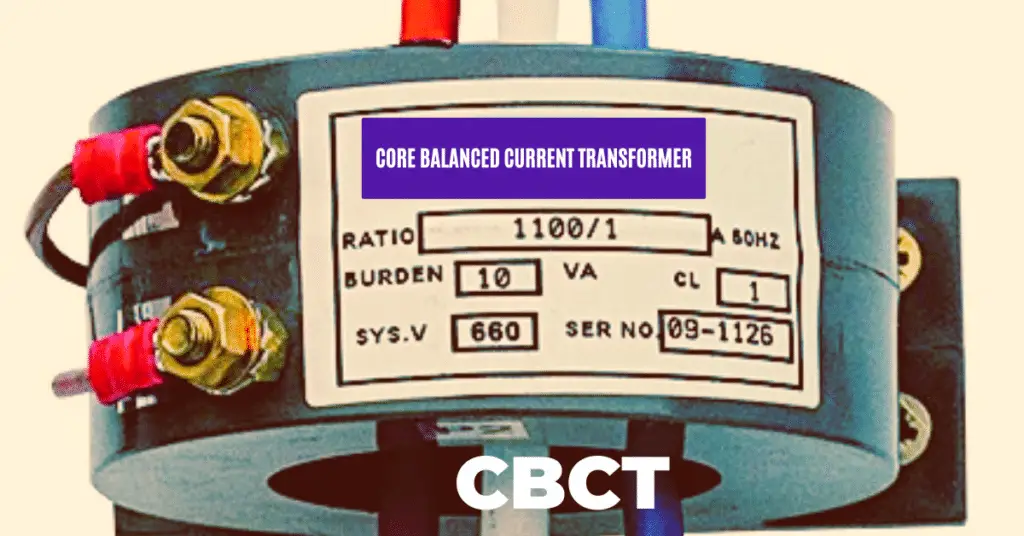
Core balance current transformer is used for detecting the earth fault in the electrical network. A current Transformer is an electrical instrument that is used for reducing the magnitude of the current passing through a conductor so that it can be measured or gauged easily using a low-range measuring or protection instrument.
Transformers transfer power from primary coils to secondary keeping the power constant by either stepping up the voltage and consequently stepping down the current or vice-versa. The current transformer also works on the same principle. It has fewer turns on the primary side (as low as 1) and higher on the secondary side. The primary coil in most cases is the current-carrying conductor itself while the secondary side has a higher number of turns and is connected to the ammeter for the purpose of measurement or is connected to a relay for the purpose of protection in case of any fault.
A Core Balance Current Transformer(CBCT) or a zero sequence current transformer(ZCT) is just like any other current transformer. The secondary coil which has a greater number of turns forms a circular ring through the center of which three single-core cables or a single three-core cable of a three-phase system passes. As mentioned earlier, this three-phase cable system forms the primary of the Core Balance Current Transformer.
Working Principle of a Core Balance Current Transformer
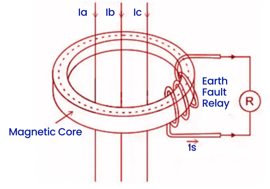
The picture above is that of a Core Balance Current Transformer (CBCT). The three-phase currents are Ia, Ib, and Ic as shown. These three-phase conductors are the primary while the secondary has been connected to the relay.
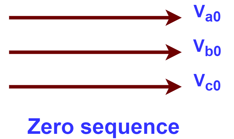
Core Balance Current Transformers work on the principle of a zero sequence current balance. Hence it is also called a Zero sequence Current Transformer (ZCT).
A zero sequence voltage or current in a three-phase system is the one when all three phases have voltages or currents equal in magnitude and all of them are in phase.
A balanced zero-sequence system is one where the algebraic sum of the zero-sequence parameters is equal to zero. It is much like Kirchoff’s current law which states that the sum of all the currents at a node is equal to zero.
Therefore during normal operation, the algebraic sum of the phase current is equal to zero.
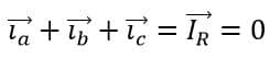
Therefore, the resultant residual current is also equal to zero and there is no fault situation so the zero sequence current is also equal to zero. The resultant magnetic field flux due to the residual current is also zero as it is directly proportional to the respective current.
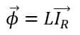
Where Φ is the magnetic field flux generated due to the resultant current IR. Lis the inductance of the coil which is a constant property. Therefore, the magnetic field flux is directly proportional to the current. As the residual current is zero, the magnetic field flux generated from the primary to link with the secondary of the CBCT is zero, and hence no current flows through the secondary of the CBCT.
During a fault like a Line-to-Earth fault or a Line leakage fault, the three-phase system no longer remains in the balanced condition as it used to and therefore the sum of the phase currents is not equal to zero. Therefore, there is a Zero sequence current of finite value generated in the system which causes a resultant magnetic field to be generated.
Let Φa, Φb, and Φc be the resultant magnetic field due to the phase currents Ia, Ib, and Ic respectively.
Therefore,
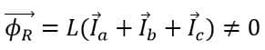
This magnetic field links with the secondary of the Core Balance Current Transformer or CBCT and causes a low-value current to flow through the secondary coil of the current transformer. This secondary coil current is supplied to a relay which activates and sends a trip signal to the circuit breaker. The circuit breaker thus operates and breaks open the supply to the fault zone, thus protecting the entire power system.
Now as discussed earlier, the zero sequence currents are equal in magnitude and are in phase. Therefore, the resultant zero sequence current is
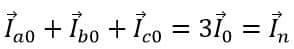
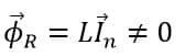
Where In is the neutral current and it is not zero during a fault or in an unbalanced system. This current generates the required magnetic field for the Core Balance Current Transformer to operate.
During a normal situation, the system remains balanced and hence the sum of the zero sequence currents is zero. Therefore no resultant magnetic field flux is generated.
This is the working principle of a Core Balance Current Transformer or a zero sequence current transformer.
Application of Core Balance Current Transformer
A Core Balance Current Transformer or CBCT is used in the protection of industrial drives i.e, three-phase induction motors against a possible line-to-earth fault or leakage fault. In this protection scheme, the core of CBCT surrounds the power cables connected with a 3-phase induction motor as shown below.
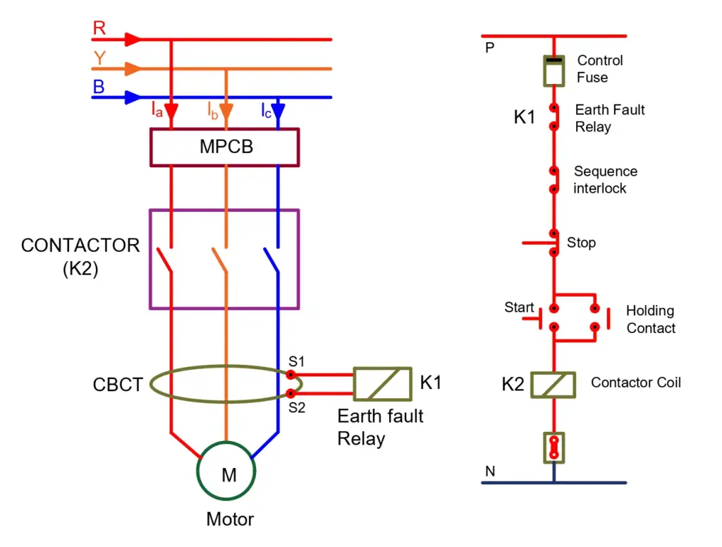
As evident from the picture above, the three-phase conductors act as the primary of the CBCT while the secondary is connected to the protection relay. During a faulty situation, the relay operates and cuts the supply to the motor thus protecting it and the subsequent power system from any further damage.
Advantages of CBCT
The main advantage of using CBCT as an earth fault protection scheme is that in this protection scheme, only one CT core is used instead of three cores as in a conventional system. Thus the magnetic flux required for the production of the secondary current is reduced to one-third (1/3), which is the biggest advantage as the overall sensitivity of the protection system increases.
Disadvantages of CBCT
The main disadvantage of a CBCT is that it requires the conductor to be completely enclosed within the transformer’s magnetic core. This means that it is not suitable for use with large conductors, as the size of the transformer would be too large and impractical.
Additionally, CBCTs can only measure the current in a single conductor at a time, which makes them less suitable for applications where multiple conductors are present.
Another disadvantage of CBCTs is that they are not suitable for measuring direct currents (DC), as they only work with alternating currents (AC).
Features of CBCT or ZCT
- Core Design: CBCTs are designed with a toroidal core, which surrounds the conductor. This core design allows the CBCT to measure the current in a non-intrusive manner.
- Accuracy: CBCTs are highly accurate, with measurement errors of typically less than 1%. This accuracy is maintained over a wide range of currents and frequencies.
- Installation: CBCTs are easy to install and do not require any interruption of the electrical supply. They can be installed by simply clamping the CBCT around the conductor.
- Safety: Since CBCTs do not require any physical connection to the conductor, they are safe to install and use. They also do not introduce any additional electrical noise into the system.
- Output Signal: CBCTs typically produce an output signal that is proportional to the current flowing through the conductor. This signal can be used for a variety of purposes, including monitoring, control, and protection.
- Size: CBCTs are available in a range of sizes, from small units for use in residential and commercial applications to larger units for use in industrial applications.
- Cost: CBCTs are generally less expensive than traditional current transformers (CTs) because they do not require a solid core or secondary winding. This makes them an attractive option for many applications.
Overall, CBCTs are a reliable and cost-effective solution for measuring AC currents in a variety of applications.