The load can be classified as a balance load and unbalance load in a polyphase electric circuit. The polyphase has two or more phases. The widely used polyphase circuits are 3-phase 3 -wire and 3-phase-4-wire systems.
Now, we will discuss more the balance and unbalanced load.
What is Balance Load?
The electrical load is the electric current drawn by electrical devices that are connected to the supply source. The devices may be a motor, heater, coil, bulb, inductor, capacitor, or any devices that have resistance, capacitor, and inductor element in it.
When the electrical devices or pieces of electrical equipment receive power from a voltage source, they draw electrical current. In an AC circuit, the magnitude of electrical current depends on the applied voltage and the impedance of the circuit. The load that draws the balance phase or line current from the constant voltage source is called the balanced load.
Balance Circuit
According to ohm’s law, the current drawn can be expressed by the following relationship.
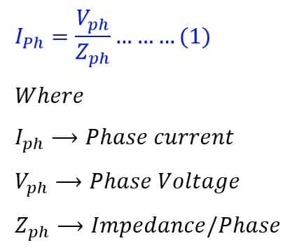
From equation (1), it is clear that each phase carries an equal current if the phase voltage and impedance per phase are equal with respect to the magnitude and phase difference. A balance circuit has the following characteristics.
- Equal Impedance in each phase
- Equal voltage in each phase
- The algebraic sum of the current of all phases is equal to zero.
- When the current in each phase is equal, it shows there is no ground fault or earth fault in a balanced circuit.
Thus, we can say the balance load is the load that draws equal current from the supply source. In other words, when a three-phase load draws an equal current in every phase, it is called a balanced load, and the circuit is said to be a balanced circuit.
When the load draws an equal current, then the algebraic sum of all the phase current is equal to zero.
Let us take an example to understand the concept of balance load.
Example of balance Circuit :
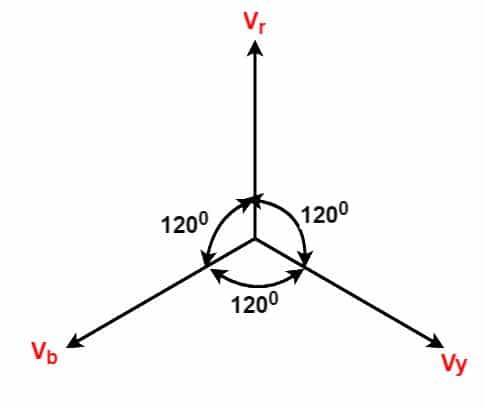
When we connect a balanced three-phase load to a three-phase balance circuit, then the current in each phase will be equal in terms of magnitude and phase angle. The input 3-phase supply has an RYB phase sequence with a 120-degree phase difference between each phase. Here, the Y phase lags the R phase by 120 degrees, and the B phase lags the Y phase by 120 degrees or leads the R phase by 120 degrees. The phasor diagram of 3-phase voltage is shown in the below diagram.
All phase voltages in the case of a balance system are equal.
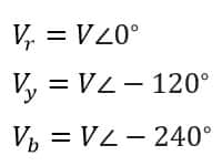
The above equation shows that the voltage is equal and the phase difference of each phase is 120 degrees.
We can prove whether a circuit has a balanced load or not by adding all the phase currents, and if the sum of all phase currents is zero then the circuit has a balanced load.
Let the current flow through the load circuits I1 , I2, and I3
The algebraic sum of current is;
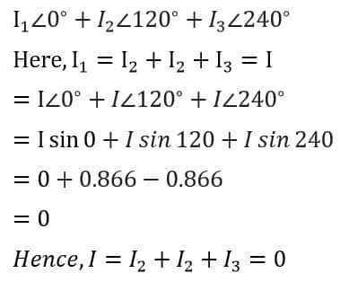
If the sum of all the phases’ current is equal to zero, it means the circuit has a balanced load.
Diagram of Balance Load (Balance Circuit)
The diagram of the balance load and the balance circuit is given below.
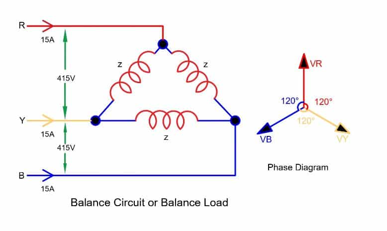
The above circuit has;
- Equal current in each phase
- Equal voltage
- The Equal Impedance
- The same phase difference in each phase
Factor Affecting Balance Circuit:
- Variation in the source voltage- The unbalance voltage cause unbalance current even when the load impedance is constant. The effect of unbalance voltage on induction motor cause deterioration in motor performance.
- Fault or loose connections in the phase circuit of star or delta connected load. For example, the open winding of the motor may cause the motor to draw unbalance current. In a similar way, an open rotor of the induction motor causes unbalance stator current.
- Single phase load connected to a three-phase system
- Any electrical fault in the system
Unbalance Load
When there is variation in voltage or impedance or both, then the load draws unbalance current. The load is said to be an unbalance load and the circuit is called unbalance circuit. This generally happens during a fault in the electrical network or fault in the electrical equipment. Under the condition of fault, the phase current becomes unequal in magnitude as well as in phase difference.
Unbalance Circuit
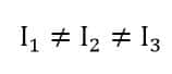
In three phase system, if one or more phase current is not equal in magnitude and phase difference, then the circuit is said to be an unbalance circuit. The phase current of each phase is unequal, in terms of magnitude and phase difference.
The unbalance circuit characteristics are as follows.
- The current in each phase is unequal
- Voltage in each phase is unequal.
- The impedance of each phase is different.
- The phase difference of each phase is not the same
- Unbalance circuit may have a flow of leakage current
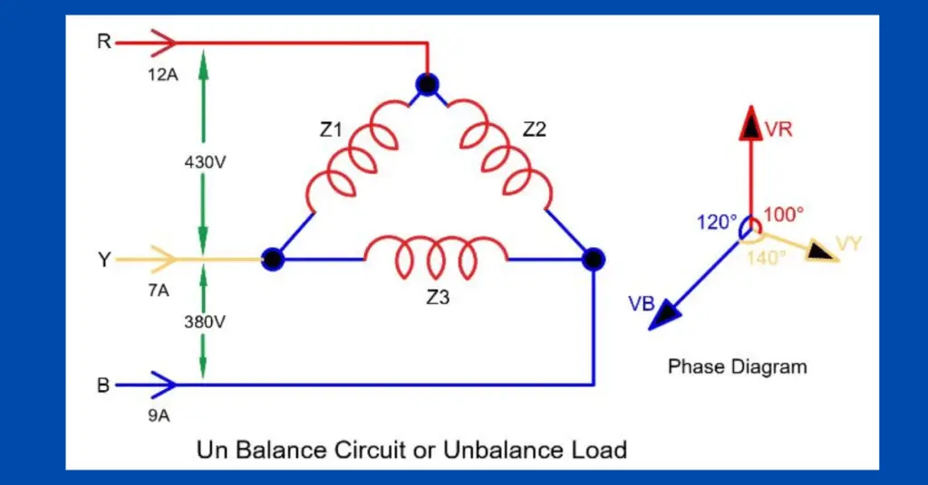
Diagram of Unbalance Load (Unbalance Circuit)
The circuit diagram of unbalance circuit and its phasor diagram is given in the below picture.
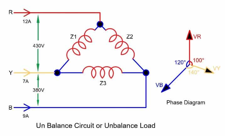
In an unbalanced circuit, the current in each phase is not identical. Also, phase voltage is not identical.
Thus, the power system efficiency and the electrical equipment performance depend on the types of balance and unbalance load connected to the system.